Zark Bedalov - Practical Power Plant Engineering
Здесь есть возможность читать онлайн «Zark Bedalov - Practical Power Plant Engineering» — ознакомительный отрывок электронной книги совершенно бесплатно, а после прочтения отрывка купить полную версию. В некоторых случаях можно слушать аудио, скачать через торрент в формате fb2 и присутствует краткое содержание. Жанр: unrecognised, на английском языке. Описание произведения, (предисловие) а так же отзывы посетителей доступны на портале библиотеки ЛибКат.

- Название:Practical Power Plant Engineering
- Автор:
- Жанр:
- Год:неизвестен
- ISBN:нет данных
- Рейтинг книги:5 / 5. Голосов: 1
-
Избранное:Добавить в избранное
- Отзывы:
-
Ваша оценка:
Practical Power Plant Engineering: краткое содержание, описание и аннотация
Предлагаем к чтению аннотацию, описание, краткое содержание или предисловие (зависит от того, что написал сам автор книги «Practical Power Plant Engineering»). Если вы не нашли необходимую информацию о книге — напишите в комментариях, мы постараемся отыскать её.
The book explores the most relevant topics and reviews the industry standards and established engineering practices. For example, the author leads the reader through the application of MV switchgear, MV controllers, MCCs and distribution lines in building plant power distribution systems, including calculations of interrupting duty for breakers and contactors. The text also contains useful information on the various types of concentrated and photovoltaic solar plants as well as wind farms with DFIG turbines. This important book:
• Explains why and how to select the proper ratings for electrical equipment for specific applications
• Includes information on the critical requirements for designing power systems to meet the performance requirements
• Presents tests of the electrical equipment that prove it is built to the required standards and will meet plant-specific operating requirements
Written for both professional engineers early in their career and experienced engineers,
is a must-have resource that offers the information needed to apply the concepts of power plant engineering in the real world.
Practical Power Plant Engineering — читать онлайн ознакомительный отрывок
Ниже представлен текст книги, разбитый по страницам. Система сохранения места последней прочитанной страницы, позволяет с удобством читать онлайн бесплатно книгу «Practical Power Plant Engineering», без необходимости каждый раз заново искать на чём Вы остановились. Поставьте закладку, и сможете в любой момент перейти на страницу, на которой закончили чтение.
Интервал:
Закладка:
The main substation on this project will contain a number of major items of equipment: transformers, HV switches, HV circuit breakers, arresters, and protection panels as well as medium voltage (MV) switchgear connected to the low voltage side of the transformers. Specifications must be urgently written for the long lead items. In this substation, the transformers should be given a priority. Large transformers are long lead items, requiring 12—18 month delivery plus the procurement time. Transformers rated up to 10 MVA can be obtained within nine months. Often, large transformers may be purchased ahead of time with a provision of being cancelled if the project is not approved to proceed. To purchase the transformers, we need know: plant load, future load, voltages, and method of cooling.
Based on the projected load estimate let us assume the main transformers will be oil immersed/forced air cooled, as follows: two (2) 230 to 13.8 kV, 30/40 MVA, YNd1, ONAN/ONAF/ONAF(prov.), BIL 900 kV, 55 °C rise at 40 °C ambient. We will explain the details later.
For our plant, each transformer must carry 30/40 MVA on ONAN/ONAF/ONAF cooling. Each stage of fan cooling adds about 15% capacity to the base rating. In addition, we can specify the transformer to have a 55/65 °C temperature rise allowance. A transformer rated at 55 °C rise has about 10% spare MVA reserve over a transformer rated 65 °C rise of the same MVA rating. Obviously, a 55 °C transformer is built to a more efficient cooling design.
We choose a single ONAF cooling stage, including a provision (prov.) for adding additional stage of cooling fans if necessary in the future.
Remember, the transformer base rating is 30 MVA. This value will be used in the study calculations.
What are the designations for the transformer cooling?
ONAN: Oil Natural Air Natural → Without fans.
ONAF: Oil Natural Air Forced → With fans.
The transformers will be furnished with a conservator tank and all the standard auxiliaries. We noted the winding configuration as YNd1. Star Primary, HV Neutral solidly (effectively) grounded, Delta secondary, lagging 30° in counter clockwise (CCW) convention. The most popular winding configurations in the industry for high voltage (HV) transformers at 230 kV and above are Yd1 and Yd11.
Transformers up to 10 MVA can be ordered as “sealed tank design,” without a conservator.
The main and plant oil immersed transformers will be placed outside, next to the plant buildings in their independent vaults with oil containment basins. The walls of the vault will be fire rated (see Chapter 4for the NFPA guidelines). The main transformers will be provided with the Deluge water mist protection system (see Chapter 22).
Furthermore, we decided that the transformers would have OnLTC in the range of ±10%. As we are 120 km away from the power plant, the voltage may not be stable. Daily 24‐hour load cycle will vary from hour to hour. The automatic tap changers will give us some form of voltage stability for the plant operation. We may also need some additional means of voltage regulation within the plant to enable us to further improve the voltage profile through power factor correction. To meet this requirement, additional capacitors and reactors may be considered (see Chapter 13).
2.6 Load Site Placement
At this conceptual phase of the engineering design, we have to determine the locations of loads within the plant as well as their kW ratings to determine the major power routes of the distribution system. Depending on the kW load magnitudes, we will determine the corresponding voltages for the distribution equipment.
| Loads (motor and feeders) up to 200 kW | 480 V, Motor voltage: 460 V |
| Loads (motors with VFDs) up to 500 kW | 480 V, Motor voltage: 460 V |
| Loads above 200 kW | 4.16 kV, Motor voltage: 4000 V |
We will obtain the load data from our mechanical engineers. Roughly, we expect that the plant‐connected load will be about 50 MW. The mining load is typically a motor load with 0.8 pf, but with power factor correction, we will get it over 0.9. This MW figure is assessed generally from the plant flow diagrams, based on the hardness of the ore, raw material processed, and product produced. In their flow diagrams, mechanical engineers may suggest a kW (HP) rating figure for each motor. However, the final kW (HP) ratings will be taken from the actual bids received from the suppliers. The tendency seems to be that suppliers more often overestimate rather than underestimate the load.
From the plant layout drawings, we determine the locations of the groups of loads: mining, crushing, conveying, grinding, process plant, tailings, and camp. The load centers will generally follow the flow of the ore. These locations may be kilometers apart from each other. The biggest groups of loads will be in the grinding and the process plant for conveying, pumping, agitation, and floatation. The camp, crushing, and tailings will be away from the process plant.
The power load centers may include either 480 V loads only, or both: 4.160 and 480 V.
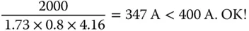
Typical 4.16 kV controllers for large motors are rated at 400 A. Controllers rated 800 A are also available, but rarely used. Let us calculate the current of a 2000 kW, pf = 0.8 motor and verify if a 4.16 kV, 400 A controller can operate it safely:
The power will be fed from the main substation to the plant load centers by 15 kV overhead lines or medium voltage (MV) cables, depending on the relative location of the main substation. In North America, the 13.8 and 4.16 kV voltages are often called 15 and 5 kV, respectively.
2.6.1 Crushing
This facility may be close to the grinding plant, but at a certain distance, to limit the dust spreading to the rest of the plant. Also a large (seven‐day) ore stockpile will be placed between the crushing station and the grinding plant. Crushing usually operates a single 12‐hour shift, while the rest of the plant marches on two shifts. A load center will be required to feed the 4 kV and 460 V motors. We will use 1.5 MVA transformers (13.2 kV/480 V or 4.16 kV/480 V) with MV controllers for motors >200 kW and 480 V MCC starters for motors rated ≤200 kW.
2.6.2 Grinding and Conveying
This is the location of the largest load, the 8 MW, (10 MVA) cyclo‐converter motor. This load is too big for 4.16 kV and must be powered at 13.8 kV. It will have its own power feeder fed directly from the main 13.8 kV switchgear located at the main substation. For this variable frequency drive (VFD), the main power supply is converted to DC voltage and then back to AC voltage of varied frequency to operate at variable speed to suit the ore quality and hardness. This large piece of equipment is a complete package. It includes a number of smaller auxiliary loads, such as MCC, fans, lube pumps, lighting, and heating, all of them fed from the same power source feeder.
The grinding facility will also need a 4.16 kV load center for MV motors (Ball Mills) and a number of load centers for a large number of low voltage (LV) motors and drives. Drives mentioned here are typically referred to as the VFD operated motors. Two grinding ball mills may even use synchronous MV motors, which by controlling their excitations may help us improve the plant power factor (see Chapter 13).
The MV load center with 5 kV switchgear and MV motor controllers will be fed from two 13.2 to 4.16 kV, 10/15 MVA, Dy11, ONAN/ONAF, oil type transformers, which will be placed outdoors adjacent to the plant and have a joint provision for oil containment.
Читать дальшеИнтервал:
Закладка:
Похожие книги на «Practical Power Plant Engineering»
Представляем Вашему вниманию похожие книги на «Practical Power Plant Engineering» списком для выбора. Мы отобрали схожую по названию и смыслу литературу в надежде предоставить читателям больше вариантов отыскать новые, интересные, ещё непрочитанные произведения.


Обсуждение, отзывы о книге «Practical Power Plant Engineering» и просто собственные мнения читателей. Оставьте ваши комментарии, напишите, что Вы думаете о произведении, его смысле или главных героях. Укажите что конкретно понравилось, а что нет, и почему Вы так считаете.