Zark Bedalov - Practical Power Plant Engineering
Здесь есть возможность читать онлайн «Zark Bedalov - Practical Power Plant Engineering» — ознакомительный отрывок электронной книги совершенно бесплатно, а после прочтения отрывка купить полную версию. В некоторых случаях можно слушать аудио, скачать через торрент в формате fb2 и присутствует краткое содержание. Жанр: unrecognised, на английском языке. Описание произведения, (предисловие) а так же отзывы посетителей доступны на портале библиотеки ЛибКат.

- Название:Practical Power Plant Engineering
- Автор:
- Жанр:
- Год:неизвестен
- ISBN:нет данных
- Рейтинг книги:5 / 5. Голосов: 1
-
Избранное:Добавить в избранное
- Отзывы:
-
Ваша оценка:
Practical Power Plant Engineering: краткое содержание, описание и аннотация
Предлагаем к чтению аннотацию, описание, краткое содержание или предисловие (зависит от того, что написал сам автор книги «Practical Power Plant Engineering»). Если вы не нашли необходимую информацию о книге — напишите в комментариях, мы постараемся отыскать её.
The book explores the most relevant topics and reviews the industry standards and established engineering practices. For example, the author leads the reader through the application of MV switchgear, MV controllers, MCCs and distribution lines in building plant power distribution systems, including calculations of interrupting duty for breakers and contactors. The text also contains useful information on the various types of concentrated and photovoltaic solar plants as well as wind farms with DFIG turbines. This important book:
• Explains why and how to select the proper ratings for electrical equipment for specific applications
• Includes information on the critical requirements for designing power systems to meet the performance requirements
• Presents tests of the electrical equipment that prove it is built to the required standards and will meet plant-specific operating requirements
Written for both professional engineers early in their career and experienced engineers,
is a must-have resource that offers the information needed to apply the concepts of power plant engineering in the real world.
Practical Power Plant Engineering — читать онлайн ознакомительный отрывок
Ниже представлен текст книги, разбитый по страницам. Система сохранения места последней прочитанной страницы, позволяет с удобством читать онлайн бесплатно книгу «Practical Power Plant Engineering», без необходимости каждый раз заново искать на чём Вы остановились. Поставьте закладку, и сможете в любой момент перейти на страницу, на которой закончили чтение.
Интервал:
Закладка:
Let us talk to the Utility to acquire the information we need to build our plant power distribution system. Here are some of the issues to be clarified by the Utility engineers:
Power agreement: firm or interruptible
Tariffs, for power demand and time of use
Line voltage and its daily and weekly profile
Frequency off‐limits
Power factor tariffs and penalties
Source impedance, inclusive of the transmission line impedance (conductors)
Double‐ or single‐circuit incoming transmission line
Generating capacity, firm power, how many units are available, and their ratings
Method of line protection
Lightning level (number of lightning days/yr) in the area
Let us review each of the aforementioned issues:
Power agreement: The plant owner will sign a power agreement with the Utility. If the plant needs power 24 hours a day, every day, the owner will look at signing a power agreement for uninterruptible firm power supply, if available. An interruptible power supply allows the utility to occasionally cut the power supply in a specific amount or in total. Naturally, this contract comes with a lower tariff. The plant owner will likely insist on an uninterruptible power supply (UPS).
Tariffs: In addition to the nominal charge for kilowatt‐hour consumed, the utility will likely have additional tariffs as demand charge, peak load, and reactive power hour consumption (MVARh consumption). The demand is the load averaged over a specified time (15 minutes, 30 minutes, or 1 hour) in kW or KVAR. The peak load may be the maximum instantaneous load or a maximum average load over a designated period of time. The reactive energy charge may be applicable for the load operating at <95% power factor at the point of interconnection (POI).
Voltage operating range: For this plant, 69, 138, and 230 kV voltages can be used. In this case, 230 kV is available and preferred. We have to determine the percentage range of voltage oscillations received from the utility and how stable it is. The next thing is to decide if our plant will need an automatic on‐load tap changers (OnLTCs) on the main incoming power transformers, or simple off‐load tap changers (OffLTCs). See a typical transformer in Figure 2.4.
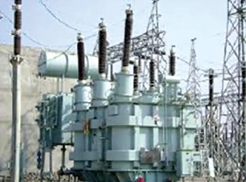
Figure 2.4 Large oil filled transformer.
Assume a 20% adder to the cost of a transformer with an automatic tap changer. On the other hand, an automatic LTC can, in addition to keeping the plant voltage constant, better regulate the flow of power and save us some money in penalties charged by the utility for the low plant power factor.
If the voltage swings are large, OffLTC changers may not be able to provide a manageable operating solution. They can regulate the plant voltage manually to a preselected percentage tap, while the OnLTCs manage the plant voltage automatically and linearly to the full tap range of ±10% on the primary winding.
If OffLTCs are employed, the operator will have to shut down the plant in order to change the taps, if desired. Naturally, manual tap changes cannot be performed on a regular daily basis. Voltage at night may be higher than during the day. So once you set the taps, that is it. You may be forced to change the tap settings again if the operating conditions alter.
Suppose, you have decided that your incoming transformers are to be rated 230 to 13.8 kV. Also, you were informed that the incoming voltage from the utility varies from 215 to 245 kV, but most likely toward the lower range (see Chapter 24for more details on transformers).
Let us examine in Table 2.1the voltage range at the secondary side of the transformers with OffLTCs for the various taps and voltage swings:
Transformer voltage: 230 to 13.8 kV
Taps on primary side range: ±10% in 2.5% steps.
Based on the aforementioned, a choice would be to operate the transformer with OffLTC at −2.5% taps for the primary voltage range of 215–245 kV. Negative taps on the transformer primary winding are the taps of choice used for boosting the plant 13.8 kV voltage. On the other hand, the OnLTC, if used, will maintain voltage relatively steady in smaller tap movements within the full tap range.
Table 2.1 Secondary voltage for primary grid voltage.
| Grid voltage | 215 kV | 230 kV | 245 kV |
| Taps set at: | |||
| −5.0% | 13.54 | 14.48 | 15.42 |
| −2.5% | 12.98 | 14.14 | 15.05 |
| 0 | 12.89 | 13.8 | 14.69 |
| +2.5% | 12.57 | 13.45 | 14.32 |
| +5.0% | 12.25 | 13.10 | 13.95 |
Most of the industrial plants would purchase transformers with OffLTCs. In this case, based on the discussions with the utility and due to the expected significant variations in the day/night voltage profile, we would prefer transformers with automatic OnLTCs to make sure we have a stable voltage in the plant at all times.
The plant voltage profile is not determined solely by the utility but also by the plant motor load. Plant reactive MVAR load will likely have to be partly drawn from the utility, as explained in Chapter 13.
The smaller plant transformers, which distribute power to lower voltages, will generally have (±5%) OffLTC tap changers. Taps for each transformer will have to be set to obtain the most comfortable voltage profile throughout the plant during the normal plant operation and for large motor starting. This can be determined by a computer load flow studyand confirmed during the plant operation. With the choice of OnLTCon our main transformers, we can consider that our plant distribution voltage will be relatively constant at 13.8 kV at all times, irrespective on what the utility throws at us.
The typical voltage drop criteria to be considered in the design of the plant distribution system is <15% for large motor starting, and <3% for large motor while running.
2.4.1 Source Impedance
This is the system subtransient impedance Z ″ representing the generating capacity of the utility at the POI. It also includes the impedance of the interconnecting transmission line. The source impedance is derived from the short‐circuit level at the plant as advised by the utility. The figure given will likely be based on a present and future generation planned by the utility. This value will be used as the base for determining the interrupting ratings of the plant circuit breakers that connect to the transmission line and the voltage regulation and capability of the plant large motors to start properly.
We have to determine the source impedance for two different extreme cases, the maximum and the minimum values, as follows:
The maximum source impedance (minimum fault level) when the utility is operating on light load with a minimum generating capacity connected to the grid. This source impedance will be used for voltage regulation calculations and large motor starting duty. If the supply network is weak (low short‐circuit level), soft, or variable frequency starting may be required for starting large motors in order to satisfy the utility flicker requirement and to minimize the impact on other nearby customers connected to the grid.
The minimum source impedance (maximum fault level) is when the utility is operating on high load with maximum generating capacity. This impedance will be used to determine the short‐circuit interrupting duty of the plant circuit breakers.
For our system studies and calculations, we will use MVA b= 30 MVA figure as our per unit MVA base. This is the base rating of our main incoming transformers: 30/40 MVA, 230 to 13.8 kV.
Читать дальшеИнтервал:
Закладка:
Похожие книги на «Practical Power Plant Engineering»
Представляем Вашему вниманию похожие книги на «Practical Power Plant Engineering» списком для выбора. Мы отобрали схожую по названию и смыслу литературу в надежде предоставить читателям больше вариантов отыскать новые, интересные, ещё непрочитанные произведения.


Обсуждение, отзывы о книге «Practical Power Plant Engineering» и просто собственные мнения читателей. Оставьте ваши комментарии, напишите, что Вы думаете о произведении, его смысле или главных героях. Укажите что конкретно понравилось, а что нет, и почему Вы так считаете.