Zhuming Bi - Computer Aided Design and Manufacturing

Здесь есть возможность читать онлайн «Zhuming Bi - Computer Aided Design and Manufacturing» — ознакомительный отрывок электронной книги совершенно бесплатно, а после прочтения отрывка купить полную версию. В некоторых случаях можно слушать аудио, скачать через торрент в формате fb2 и присутствует краткое содержание. Жанр: unrecognised, на английском языке. Описание произведения, (предисловие) а так же отзывы посетителей доступны на портале библиотеки ЛибКат.

Computer Aided Design and Manufacturing: краткое содержание, описание и аннотация

Предлагаем к чтению аннотацию, описание, краткое содержание или предисловие (зависит от того, что написал сам автор книги «Computer Aided Design and Manufacturing»). Если вы не нашли необходимую информацию о книге — напишите в комментариях, мы постараемся отыскать её.

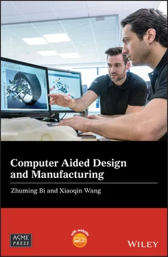
Broad coverage of digital product creation, from design to manufacture and process optimization This book addresses the need to provide up-to-date coverage of current CAD/CAM usage and implementation. It covers, in one source, the entire design-to-manufacture process, reflecting the industry trend to further integrate CAD and CAM into a single, unified process. It also updates the computer aided design theory and methods in modern manufacturing systems and examines the most advanced computer-aided tools used in digital manufacturing.
Computer Aided Design and Manufacturing being uniquely structured to classify and align engineering disciplines and computer aided technologies from the perspective of the design needs in whole product life cycles, utilizing a comprehensive Solidworks package (add-ins, toolbox, and library) to showcase the most critical functionalities of modern computer aided tools, and presenting real-world design projects and case studies so that readers can gain CAD and CAM problem-solving skills upon the CAD/CAM theory.
is an ideal textbook for undergraduate and graduate students in mechanical engineering, manufacturing engineering, and industrial engineering. It can also be used as a technical reference for researchers and engineers in mechanical and manufacturing engineering or computer-aided technologies.
Computer Aided Design and Manufacturing — читать онлайн ознакомительный отрывок

Ниже представлен текст книги, разбитый по страницам. Система сохранения места последней прочитанной страницы, позволяет с удобством читать онлайн бесплатно книгу «Computer Aided Design and Manufacturing», без необходимости каждый раз заново искать на чём Вы остановились. Поставьте закладку, и сможете в любой момент перейти на страницу, на которой закончили чтение.

Тёмная тема
Сбросить

Интервал:

Закладка:

Сделать

9 Chapter 9Figure 9.1 Production facilities in a manufacturing system (Groover 2007).Figure 9.2 Humans and machines in a manufacturing system (Williams and Li 1998...Figure 9.3 Automated decision‐making supports in manufacturing.Figure 9.4 Level of automation in a manufacturing execution system (MES).Figure 9.5 Typical production facilities supported by CAM. (a) Numerically con...Figure 9.6 Controllable variables in three FFSs. (a) Modular fixture. (b) Adap...Figure 9.7 Difference of NC and CNC machines. (a) NC system. (b) CNC system.Figure 9.8 A central computer for the controls of DNCs.Figure 9.9 Example of machining centre (Kasugai et al. 2003).Figure 9.10 Numerical control working principle.Figure 9.11 Examples of stock shapes. (a) Sheet. (b) Block. (c) Tube. (d) Beam...Figure 9.12 Examples of machined parts. (a) Part with turned features. (b) Par...Figure 9.13 Types of conventional machining processes.Figure 9.14 Process parameters in a turning operation.Figure 9.15 Examples of the moving components in a CNC machine tool.Figure 9.16 The workflow of CNC programming.Figure 9.17 Right‐hand rule for the definition of coordinate systems and motio...Figure 9.18 Default coordinate planes for a mill machine.Figure 9.19 Default two‐axis coordinate system on a CNC lathe.Figure 9.20 Tool reference zero ( R ), part reference zero ( W ), and machine refe...Figure 9.21 Absolute coordinates measured from the origin of the coordinate sy...Figure 9.22 Example of absolute coordinates. (a) Tag points on path. (b) Absol...Figure 9.23 Example of absolute coordinates for lathe. (a) Working points on a...Figure 9.24 Incremental coordinates measuring relative displacements of points...Figure 9.25 Example of incremental coordinates. (a) Tag points on path. (b) In...Figure 9.26 Common types of motion paths. (a) Point to point motion (drilling ...Figure 9.27 NC example code from APT.Figure 9.28 Example of a milling path.Figure 9.29 The block structure of an NC statement.Figure 9.30 A straight‐line path by G01 motion command.Figure 9.31 A clock‐wise arc path by G02 in XY , XZ , and YZ planes. (a) XY plan...Figure 9.32 Example of NC programming for a drilling operation.Figure 9.33 The steps of drilling operations in Example 9.5.Figure 9.34 The NC program for the drilling operation in Example 9.5.Figure 9.35 Example of CN programming with arc motions. (a) Contouring operati...Figure 9.36 The features of HSMWorks as a 2.5‐ to 5‐axis CAD/CAM solution.Figure 9.37 Programming interface of HSMWorks. (a) User‐friendly programming i...Figure 9.38 Part CAD models for Problem 9.1.Figure 9.39 Part CAD model for Problem 9.2.Figure 9.40 Exemplifying machined parts for design project.

10 Chapter 10Figure 10.1 Description of a manufacturing process.Figure 10.2 Shaping processes in classification of manufacturing processes.Figure 10.3 Classification of shaping processes based on working temperatures.Figure 10.4 Impact of computer aided techniques on cost reduction of manufactu...Figure 10.5 Inputs and outputs of designing and planning of a manufacturing pr...Figure 10.6 Types of starting materials in different shaping processes.Figure 10.7 Raw materials and products of casting processes.Figure 10.8 Examples of casting products.Figure 10.9 Typical setup of casting processes.Figure 10.10 Classification of casting processes.Figure 10.11 Partial structure of sprue and runner designs for Example 10.2.Figure 10.12 Riser design example.Figure 10.13 Common defect types in sand casting.Figure 10.14 Definition of a draft for casting.Figure 10.15 Steps and activities in a casting process.Figure 10.16 Components used in casting processes.Figure 10.17 Functional models of AutoCAST (Ravi 2017).Figure 10.18 Product examples from injection moulding processes.Figure 10.19 Machinery for injection moulding.Figure 10.20 Machine selection based on product weight and machine capacity.Figure 10.21 The steps in a cycle of injection moulding.Figure 10.22 Temperature and pressure for moldability of injection moulding pr...Figure 10.23 The flowchart of designing an injection moulding system.Figure 10.24 Inputs and outputs of computer aided moulding filling analysis.Figure 10.25 The development of a weldline.Figure 10.26 The defected mould with flashes.Figure 10.27 The defected mould with short shots.Figure 10.28 The defected mould with warpages.Figure 10.29 The defected mould with sink marks.Figure 10.30 Activating a SolidWorks Plastics tool.Figure 10.31 Steps in mould analysis wizard.Figure 10.32 Interfaces in the steps of generate mesh and injection location .Figure 10.33 Review mould filling analysis results.Figure 10.34 Commonly used simulation data in mould filling analysis.Figure 10.35 Available tools in SolidWorks Plastics.Figure 10.36 Example of product and mould filling analysis for Design Project...

11 Chapter 11Figure 11.1 Examples of machining tools for conventional material removal proc...Figure 11.2 Examples of moulds and dies for forming and deforming processes: (...Figure 11.3 Role of TDM industry in manufacturing (Lanzuela 2018).Figure 11.4 Examples of diversified functional tools for different processes. ...Figure 11.5 Cost constitutions of the TDM product.Figure 11.6 Statistic data of average lead time of dies and tools for customer...Figure 11.7 Examples of injection moulded products: (a) furniture, (b) toys, (...Figure 11.8 Construction of a typical injection mould.Figure 11.9 The number of cavities versus unit product cost.Figure 11.10 Symmetric configuration of running systems for balancing melt flo...Figure 11.11 Runners with modified trapezoid profiles.Figure 11.12 Four basic types of runner layouts: (a) standard (herringbone), (...Figure 11.13 Examples of unbalanced runner systems: (a) unbalanced star layout...Figure 11.14 Examples of balanced runner systems: (a) standard (herringbone), ...Figure 11.15 Example of branched runners and clod slug.Figure 11.16 The length of clod slug ( L well≥ d main).Figure 11.17 Main components in a sprue design.Figure 11.18 Guides to position gates in a running system.Figure 11.19 The impact of the gating system on mechanical properties: (a) inf...Figure 11.20 Two basic gate types: (a) edge gate and (b) fan gate.Figure 11.21 Gate types by automatic trimming (Mold Technology 2011b). (a) A s...Figure 11.22 Common types of ejections: (a) pin ejection, (b) sleeve ejection,...Figure 11.23 Cooling system for uniform temperature distribution. (a) Unfavour...Figure 11.24 The distance of cooling channels to part.Figure 11.25 Mould components in part examples: (a) phone cover and (b) plasti...Figure 11.26 Graphical user interface of a mould module.Figure 11.27 Procedure of a computer aided mould design.Figure 11.28 Scale a part model to compensate shrinkage: (a) access Scalein I...Figure 11.29 Running a draft analysis.Figure 11.30 Adding drafts on surfaces.Figure 11.31 Creating a parting line.Figure 11.32 Creating a parting surface.Figure 11.33 Creating core and cavity by Tooling Split .Figure 11.34 Visualization of a mould assembly. (a) Intermediate features in c...Figure 11.35 Combine and save selected bodies as an individual part model. (a)...Figure 11.36 Examples of sheet moulding compound products in an automobile (As...Figure 11.37 Illustration of compression moulding process.Figure 11.38 Example of compression moulding simulation in Autodesk Modflow (L...Figure 11.39 Simulation of a draping process and example (Hinterhölzl 2014): (...Figure 11.40 Deformations of composites in the draping process (Hinterhölzl 20...Figure 11.41 Geometric approach for evaluation of distortion (Hinterhölzl 2014...Figure 11.42 Activating the surface flatten tool in SolidWorks.Figure 11.43 Using the surface flatten tool in SolidWorks.Figure 11.44 Flatten the surface as a feature of the part model.Figure 11.45 Viewing the deformation.Figure 11.46 Comparison of deformations with/without stress relief cuts: (a) w...Figure 11.47 Failure in creating a flattened surface for the entire part surfa...Figure 11.48 Segmentation technique applied to a complex non‐smooth part: (a) ...Figure 11.49 Example of an injection moulded part for Design Project 1.Figure 11.50 Sample mould assembly for an injection moulded part.

Читать дальше
Тёмная тема
Сбросить

Интервал:

Закладка:

Сделать

Похожие книги на «Computer Aided Design and Manufacturing»

Представляем Вашему вниманию похожие книги на «Computer Aided Design and Manufacturing» списком для выбора. Мы отобрали схожую по названию и смыслу литературу в надежде предоставить читателям больше вариантов отыскать новые, интересные, ещё непрочитанные произведения.


Отзывы о книге «Computer Aided Design and Manufacturing»

Обсуждение, отзывы о книге «Computer Aided Design and Manufacturing» и просто собственные мнения читателей. Оставьте ваши комментарии, напишите, что Вы думаете о произведении, его смысле или главных героях. Укажите что конкретно понравилось, а что нет, и почему Вы так считаете.

x