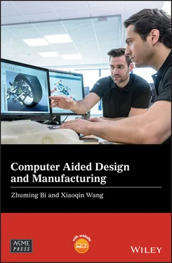
Zhuming Bi - Computer Aided Design and Manufacturing

Здесь есть возможность читать онлайн «Zhuming Bi - Computer Aided Design and Manufacturing» — ознакомительный отрывок электронной книги совершенно бесплатно, а после прочтения отрывка купить полную версию. В некоторых случаях можно слушать аудио, скачать через торрент в формате fb2 и присутствует краткое содержание. Жанр: unrecognised, на английском языке. Описание произведения, (предисловие) а так же отзывы посетителей доступны на портале библиотеки ЛибКат.

Computer Aided Design and Manufacturing: краткое содержание, описание и аннотация

Предлагаем к чтению аннотацию, описание, краткое содержание или предисловие (зависит от того, что написал сам автор книги «Computer Aided Design and Manufacturing»). Если вы не нашли необходимую информацию о книге — напишите в комментариях, мы постараемся отыскать её.

Broad coverage of digital product creation, from design to manufacture and process optimization This book addresses the need to provide up-to-date coverage of current CAD/CAM usage and implementation. It covers, in one source, the entire design-to-manufacture process, reflecting the industry trend to further integrate CAD and CAM into a single, unified process. It also updates the computer aided design theory and methods in modern manufacturing systems and examines the most advanced computer-aided tools used in digital manufacturing.
Computer Aided Design and Manufacturing being uniquely structured to classify and align engineering disciplines and computer aided technologies from the perspective of the design needs in whole product life cycles, utilizing a comprehensive Solidworks package (add-ins, toolbox, and library) to showcase the most critical functionalities of modern computer aided tools, and presenting real-world design projects and case studies so that readers can gain CAD and CAM problem-solving skills upon the CAD/CAM theory.
is an ideal textbook for undergraduate and graduate students in mechanical engineering, manufacturing engineering, and industrial engineering. It can also be used as a technical reference for researchers and engineers in mechanical and manufacturing engineering or computer-aided technologies.
Computer Aided Design and Manufacturing — читать онлайн ознакомительный отрывок

Ниже представлен текст книги, разбитый по страницам. Система сохранения места последней прочитанной страницы, позволяет с удобством читать онлайн бесплатно книгу «Computer Aided Design and Manufacturing», без необходимости каждый раз заново искать на чём Вы остановились. Поставьте закладку, и сможете в любой момент перейти на страницу, на которой закончили чтение.

Тёмная тема
Сбросить

Интервал:

Закладка:

Сделать

6 Chapter 6Figure 6.1 Multiple design constraints and criteria in optimization.Figure 6.2 Growing complexity of design of modern machines.Figure 6.3 Example of complexity growth of machine design. (a) Traditional mac...Figure 6.4 Main steps in a machine design process.Figure 6.5 Classification of links. (a) Binary link. (b) Quaternary link. (c) ...Figure 6.6 Free object and its degrees of freedom (DoF) of motion. (a) Six DoF...Figure 6.7 Classification of joints and the degrees of freedom of motion. (a) ...Figure 6.8 Classification of kinematic chains. (a) Open‐loop. (b) Closed loop....Figure 6.9 Examples of simple machines. (a) Package mover on an assembly bench...Figure 6.10 Mobility of a quick‐return mechanism. (a) Indexed links. (b) Index...Figure 6.11 Mobility of a pumping mechanism. (a) Indexed links. (b) Indexed jo...Figure 6.12 Mobility evaluation for industrial robots. (a) Articulated robot. ...Figure 6.13 Basic mechanisms of machine elements. (a) Eye‐bar type link (the l...Figure 6.14 Examples of 16 different four‐bar mechanisms in type synthesis. (a...Figure 6.15 Kinematic chains with 0, 1, and 2 DoFs, requiring 0, 1, and 2 inpu...Figure 6.16 Over‐actuated kinematic example.Figure 6.17 A position of particle in 2D and 3D space. (a) Particle P in the O ...Figure 6.18 A line in 2D and 3D space. (a) Line A–B in the O‐XY plane. (...Figure 6.19 An object in 3D space. (a) Object in 3D space. (b) Correspondence ...Figure 6.20 A motion of a particle in 2D and 3D space. (a) In the O‐XY p...Figure 6.21 General motion of a link in 2D space.Figure 6.22 General motion of a body in 3D space. (a) Translation and rotation...Figure 6.23 Rotation along the axes of CS. (a) Rotation along the X ‐axis. (b) ...Figure 6.24 Vector‐loop method for a four‐bar mechanism.Figure 6.25 A parametric model of a tripod system configuration. (a) System co...Figure 6.26 Kinematic constraints.Figure 6.27 D‐H convention from frame I – 1 to frame i .Figure 6.28 D‐H convention for a forward kinematic problem.Figure 6.29 Jacobian matrix for relation of velocities.Figure 6.30 D‐H convention for a forward kinematic problem.Figure 6.31 Structure of Puma 560.Figure 6.32 Inertia and moment of inertia of mass and body. (a) Inertia for li...Figure 6.33 Example of principal coordinate system.Figure 6.34 Newton and Euler laws. (a) Force causes linear acceleration ( F= m Figure 6.35 Free‐Body‐Diagram (FBD) of link i in frame i .Figure 6.36 Mass centres and force analysis of a tripod mechanism.Figure 6.37 Joint accelerations.Figure 6.38 Joint forces calculated from the dynamic model.Figure 6.39 Discrepancy of theoretical and measured results of the joint force...Figure 6.40 Lagrangian formulation for dynamic modelling of a two DoF robot.Figure 6.41 Steps of using a computer aided tool in a virtual machine design.Figure 6.42 Main functional modules for a virtual machine design in SolidWorks...Figure 6.43 Mates in assembly modelling of SolidWorks. (a) Standard mates. (b)...Figure 6.44 Assembly modelling of an ABB yumi robot. (a) 14 joints (ABB 2018)....Figure 6.45 Create a Motion Study for a machine model. (a) Activate Motion in Figure 6.46 Types of motion variables in a Motion Study.Figure 6.47 Defining a motor in a SolidWorks Motion Study.Figure 6.48 Interfaces for the settings of a simulation model. (a) Activate Mo ...Figure 6.49 Run simulation and visualize motion.Figure 6.50 Review the results of kinematic and dynamic variables. (a). Activa...Figure 6.51 Review the results of kinematic and dynamic variables.Figure 6.52 Mechanical event simulation in a motion analysis model.Figure 6.53 Example of a Motion Analysis design project. (a) Dimensions of th...

7 Chapter 7Figure 7.1 Example of unorganized machine shop.Figure 7.2 Manufacturing system model (Bi et al. 2008).Figure 7.3 Breakdown of costs for a manufactured product (Black 1991).Figure 7.4 Ideal system paradigm versus volumes and variations of products.Figure 7.5 Main components in a manufacturing system (Bi et al. 2008).Figure 7.6 Typical types of machine tools.Figure 7.7 Layout types of manufacturing systems.Figure 7.8 Functional or process layout.Figure 7.9 Product layout.Figure 7.10 Example of project shop (AQT Solution 2016; Song and Woo 2013).Figure 7.11 Example of continuous products (HIBA 2019).Figure 7.12 Cellular manufacturing layout.Figure 7.13 Example of flexible manufacturing system (O'Sullivan 2019; BrainKa...Figure 7.14 Classification of FMSs based on material flow layouts. (a) Progres...Figure 7.15 Scenario of distributed manufacturing (Mahdabi et al. 2007).Figure 7.16 Example of inappropriate part family by visual inspection. (a) Pla...Figure 7.17 Example of organizing products into families. (a) Unorganized prod...Figure 7.18 Examples of product families with and without the geometric simila...Figure 7.19 Comparative rankings for major parameters of sheet metal products ...Figure 7.20 Three types of coding structures (Askin and Standridge 1993).Figure 7.21 Hierarchical structure of a monocode.Figure 7.22 Details of a monocode.Figure 7.23 Example of using a coding system to code products. (a) Example of ...Figure 7.24 Example of converting a polycode scheme into digital representatio...Figure 7.25 Example of coding products by a polycode. (a) Car model. (b) Code ...Figure 7.26 Hybrid code example. (a) Polycode. (b) Monocode. (c) Polycode.Figure 7.27 Structure of the Opitze coding system.Figure 7.28 Product drawing for Example 7.5.Figure 7.29 Product drawings for Example 7.6. (a) Dimension. (b) 3D part view.Figure 7.30 Merging product features for a composite product. (a) Instance 1 (...Figure 7.31 Composite product for the determination of machines and tools. (a)...Figure 7.32 Potential benefits of implementing GT and CM.Figure 7.33 Product variants for Design Problem 7.4. (a) Chamber. (b) Through...

8 Chapter 8Figure 8.1 Typical tasks in process planning of discrete manufacturing.Figure 8.2 Discrepancy of actual and planned paths caused by the cutting force...Figure 8.3 Drill jig example.Figure 8.4 Common solutions for an integration of clamping and guiding (Mechan...Figure 8.5 Degree of freedoms (DoF) of a solid body.Figure 8.6 Three types of main components in a fixture system.Figure 8.7 The 3‐2‐1 principle in fixture design.Figure 8.8 Three locators on the primary plane eliminate 3 DoF and the motion ...Figure 8.9 The secondary and tertiary planes remove 2 and 1 DoF on the object,...Figure 8.10 Example of using the primary plane for geometric tolerance.Figure 8.11 Common fixture setup for a cylindrical object.Figure 8.12 The object restricted by a number of contacts and the free‐body di...Figure 8.13 Typical elements used in a fixturing system (Keyvani 2008).Figure 8.14 Common component supports. (a) Sub plate. (b) Sine plate. (c) Righ...Figure 8.15 Fixture types based on generality of uses.Figure 8.16 Examples of general‐purpose fixtures. (a) Vise. (b) Versatile vise...Figure 8.17 Examples of dedicated fixtures. (a) Tombstone fixture. (b) Milling...Figure 8.18 Fixture types based on generality of uses. (a) Round locator. (b) ...Figure 8.19 Examples of clamping mechanisms. (a) Strap clamp. (b) Screw clamp....Figure 8.20 Evolution of work‐holding techniques (Gameros et al. 2017).Figure 8.21 Adjustable work‐holding by Walczyk et al. (1999).Figure 8.22 Adjustable work‐holding by Chan and Lin (1996).Figure 8.23 Examples of adjustable fixtures. (a) Circular adjustment I. (b) Ci...Figure 8.24 Two examples of modular fixtures. (a) Modular fixture example 1: h...Figure 8.25 Types of locating techniques in modular fixtures (Bi and Zhang 200...Figure 8.26 Example of a flexible fixture using phase‐change materials (Hazen ...Figure 8.27 Example of a conformable fixture.Figure 8.28 Grippers for fixtureless operations.Figure 8.29 Relations of a fixture design with other planning tasks in the pro...Figure 8.30 Key design factors and criteria of a fixture design.Figure 8.31 Overview of fixture verification systems (Wang et al. 2010).Figure 8.32 History of the applications of a computer aided fixture design.Figure 8.33 Framework of a computer aided fixture design.Figure 8.34 Design library example of functional modules for CAFD (Li 2009). (...Figure 8.35 Example of interference detection (Li 2009). (a) Exploded view. (b...Figure 8.36 Examples of an accessibility study (Ghappande 2008).Figure 8.37 Example of deformation and accuracy analysis (Kaya 2006).Figure 8.38 Workpiece example of the design project (1).Figure 8.39 2D fixture parameters and tool path direction for the design proje...

Читать дальше
Тёмная тема
Сбросить

Интервал:

Закладка:

Сделать

Похожие книги на «Computer Aided Design and Manufacturing»

Представляем Вашему вниманию похожие книги на «Computer Aided Design and Manufacturing» списком для выбора. Мы отобрали схожую по названию и смыслу литературу в надежде предоставить читателям больше вариантов отыскать новые, интересные, ещё непрочитанные произведения.


Отзывы о книге «Computer Aided Design and Manufacturing»

Обсуждение, отзывы о книге «Computer Aided Design and Manufacturing» и просто собственные мнения читателей. Оставьте ваши комментарии, напишите, что Вы думаете о произведении, его смысле или главных героях. Укажите что конкретно понравилось, а что нет, и почему Вы так считаете.

x