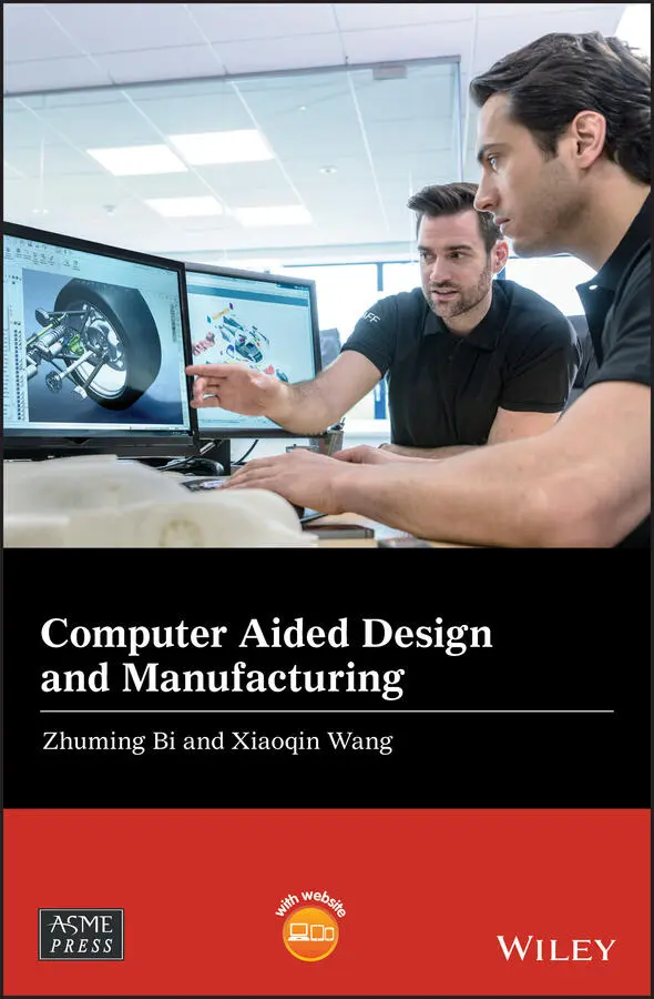
Zhuming Bi - Computer Aided Design and Manufacturing
Здесь есть возможность читать онлайн «Zhuming Bi - Computer Aided Design and Manufacturing» — ознакомительный отрывок электронной книги совершенно бесплатно, а после прочтения отрывка купить полную версию. В некоторых случаях можно слушать аудио, скачать через торрент в формате fb2 и присутствует краткое содержание. Жанр: unrecognised, на английском языке. Описание произведения, (предисловие) а так же отзывы посетителей доступны на портале библиотеки ЛибКат.
- Название:Computer Aided Design and Manufacturing
- Автор:
- Жанр:
- Год:неизвестен
- ISBN:нет данных
- Рейтинг книги:3 / 5. Голосов: 1
-
Избранное:Добавить в избранное
- Отзывы:
-
Ваша оценка:
Computer Aided Design and Manufacturing: краткое содержание, описание и аннотация
Предлагаем к чтению аннотацию, описание, краткое содержание или предисловие (зависит от того, что написал сам автор книги «Computer Aided Design and Manufacturing»). Если вы не нашли необходимую информацию о книге — напишите в комментариях, мы постараемся отыскать её.
Computer Aided Design and Manufacturing being uniquely structured to classify and align engineering disciplines and computer aided technologies from the perspective of the design needs in whole product life cycles, utilizing a comprehensive Solidworks package (add-ins, toolbox, and library) to showcase the most critical functionalities of modern computer aided tools, and presenting real-world design projects and case studies so that readers can gain CAD and CAM problem-solving skills upon the CAD/CAM theory.
is an ideal textbook for undergraduate and graduate students in mechanical engineering, manufacturing engineering, and industrial engineering. It can also be used as a technical reference for researchers and engineers in mechanical and manufacturing engineering or computer-aided technologies.
Computer Aided Design and Manufacturing — читать онлайн ознакомительный отрывок
Ниже представлен текст книги, разбитый по страницам. Система сохранения места последней прочитанной страницы, позволяет с удобством читать онлайн бесплатно книгу «Computer Aided Design and Manufacturing», без необходимости каждый раз заново искать на чём Вы остановились. Поставьте закладку, и сможете в любой момент перейти на страницу, на которой закончили чтение.
Интервал:
Закладка:
5 Chapter 5Table 5.1 Critical activities in a surface reconstruction algorithm (Bi and Kang...Table 5.2 Lookup table for determination of the weights.Table 5.3 Comparison of three algorithms on different point clouds (Bi and Kang ...Table 5.4 Typical contact devices for reverse engineering (Pham and Hieu 2008).Table 5.5 Some manufacturers and data acquisition devices (Ingensand 2016; Boehl...Table 5.6 Independent 3D scanning software tools.Table 5.7 Trend of reverse engineering (RE) techniques (Gonuke 2017).
6 Chapter 6Table 6.1 Categories of FRs in machine design.Table 6.2 Steps of orientation transformation by Euler angles.Table 6.3 Dynamic parameters.Table 6.4 Comparison of SolidWorks Animation, Basic Motion, and Motion Analysis.
7 Chapter 7Table 7.1 Characteristics of process layout (job shop).Table 7.2 Characteristics of product layout (flow shop).Table 7.3 Characteristics of fixed position layout (project shop).Table 7.4 Characteristics of continuous production (Knowledgiate Team 2017).Table 7.5 Characteristics of cellular manufacturing (Weber 2004).Table 7.6 Categories of FMS layout (O'Sullivan 2019; BrainKart 2019).Table 7.7 Characteristics of flexible manufacturing systems (CPV 2019).Table 7.8 The types of networked models for distributed manufacturing (Rauch and...Table 7.9 Design and manufacturing attributes for similarities.Table 7.10 Example of polycode.Table 7.11 Polycode structure for Nissan passenger cars.Table 7.12 Constitutions of the Opitz code.Table 7.13 Roles of digits in the Opitz coding system.Table 7.14 Coding product features in Opitz coding system.Table 7.15 Main tasks in design of CM (Strategosinc 2019).Table 7.16 Statistic survey of benefits of CMs (Hyer and Wemmerlov 2001).
8 Chapter 8Table 8.1 Comparison of continuous manufacturing and discrete manufacturing.Table 8.2 Difference of jigs and fixtures.Table 8.3 Other quantifiable evaluation criteria in fixture design.Table 8.4 The tasks at four stages of fixture design.
9 Chapter 9Table 9.1 The comparison of NC and CNC machines (Engineeringinsider 2019).Table 9.2 Main activities involved in CNC programming.Table 9.3 Motion nomenclatures of machine tools.Table 9.4 NC program for the milling operation of part in Figure 9.28.Table 9.5 Steps and tasks for CNC programming in CAM.Table 9.6 Five types of words in G‐code.Table 9.7 Commonly used G words.Table 9.8 Commonly used M words.
10 Chapter 10Table 10.1 Casting processes – advantages and disadvantages.Table 10.2 Recommended pattern shrinkage allowance.Table 10.3 Modification of product features for casting processes.Table 10.4 Concepts and main components in a casting system.Table 10.5 Typical shrinkage compensation for commonly used plastics.
11 Chapter 11Table 11.1 Machinery and tooling in conventional manufacturing processes.Table 11.2 Import and export trades of TDM from 1997 to 2010 (Canis 2012).Table 11.3 The shrinkages of American manufacturing and TDM industry (Canis 2012...Table 11.4 Recommended runner dimensions based on maximum runner lengths.Table 11.5 General guides to position gates.aTable 11.6 Recommended distances (Mold Technology 2011c).Table 11.7 Comparison of kinematic and finite element approaches (Hinterhölzl 20...
12 Chapter 12Table 12.1 Industry evolution from Industry 1.0 to 4.0.Table 12.2 Fifteen representative digital technologies in DM (PWC 2017).Table 12.3 Technical specifications of Dell EMC Ready Solutions (Dell 2019).Table 12.4 Fifteen object types in Simio object library (Simio 2019b).Table 12.5 Predicted needs of printing jobs for students in different courses at...
13 Chapter 13Table 13.1 The timeline of AM application (Tamburrino et al. 2015).Table 13.2 AM – advantages and disadvantages (Sinha 2016).Table 13.3 Supply chain for subtractive and additive manufacturing (Frost and Su...Table 13.4 The interface, steps, and settings to export an .STL file from SolidW...Table 13.5 Surface roughness of AM technique (Campbell et al. 2002; Kumbhar and ...Table 13.6 Practical options for post‐processing for improvement of surface fini...Table 13.7 Examples of commonly used AM techniques and applicable materials (Und...
14 Chapter 14Table 14.1 DOWNTIME and environmental impact (EPA 2017).Table 14.2 Six stages of LCA in SolidWorks Sustainability (Planchard 2019).
List of Illustrations
1 Chapter 1 Figure 1.1 A manufacturing system can be very simple or complex (a). Blacksmit... Figure 1.2 Description of a manufacturing system. Figure 1.3 The growth of scale and complexity of manufacturing systems (Bi et ... Figure 1.4 Human's role in manufacturing (Ortiz et al. 1999). Figure 1.5 The strategies, domains, and production paradigms of advanced manuf... Figure 1.6 Evolution of computer aided technologies in manufacturing (Bi and C... Figure 1.7 Significant impact of design activities on overall product cost. Figure 1.8 Value‐added chain smile curve (IEC 2019; ITC 2019). Figure 1.9 Relative costs to fix errors at different phases of product lifecyc... Figure 1.10 Human designers and computers in engineering design. Figure 1.11 Architecture of computer aided systems. Figure 1.12 Evolution of computer hardware (Moravec 1998). Figure 1.13 Evolution of semiconductors for processors (Computer History 2019a... Figure 1.14 Main types of computer memories (Computer History 2019b). Figure 1.15 Types of peripheral devices for inputs and outputs. Figure 1.16 Computer aided software system architecture. Figure 1.17 Computer aided collaboration in virtual environment (Wu et al. 201... Figure 1.18 CATs in designing, manufacturing, and assembling and system integr... Figure 1.19 Typical computer aided tools in CAD, CAM, and CAD/CAM. Figure 1.20 The evolution of computer aided technologies in manufacturing, (a)... Figure 1.21 Mismatch of subdisciplines and computer aided tools in manufacturi... Figure 1.22 Proposed course framework for digital manufacturing. Figure 1.23 Selective subjects in a new CAD/CAM course. Figure 1.24 Selective concepts in the CAD/CAM theory. Figure 1.25 Selective CAD/CAM tools. Figure 1.26 Customized outline of the CAD/CAM book.
2 Chapter 2 Figure 2.1 Role of geometric modelling in computer aided systems (CAD). Figure 2.2 Example of basic geometric elements. (a) Points, nodes, lines, edge... Figure 2.3 Three commonly used coordinate systems. (a) Cartesian coordinate sy... Figure 2.4 Default Cartesian CS in a CAD system. Figure 2.5 The definition of a point from existing reference geometries. (a) A... Figure 2.6 Using points to represent lines and planes. (a) Point. (b) Line. (c... Figure 2.7 The definition of a reference line from existing geometric elements... Figure 2.8 The definition of a reference plane from existing geometric element... Figure 2.9 Object coordinate system in a world coordinate system. Figure 2.10 Impacts of elements in a generalized homogeneous matrix. Figure 2.11 Example of a scaling matrix of a 3D object. (a) Before transformat... Figure 2.12 Reflection coordinate transformation matrices of an object. (a) Ob... Figure 2.13 Example of the 3D shearing transformation of an object. (a) Before... Figure 2.14 Rational coordinate transformation of an object. (a) Object in the... Figure 2.15 Vertices, edges, and faces of a solid. Figure 2.16 Relational structure of a pyramid object. Figure 2.17 Hierarchical structure of a pyramid object. Figure 2.18 Network structure of a pyramid object. Figure 2.19 Representation of a spherical surface. Figure 2.20 Examples of valid and invalid geometries. (a) Same geometries with... Figure 2.21 Inner loop and genus examples. (a) Inner loop example. (b) Genus e... Figure 2.22 Variety of geometric modelling methods. Figure 2.23 Ambiguity examples of wireframe models. (a) Wireframe model. (b) P... Figure 2.24 Surface model example. Figure 2.25 Example of half‐spaces in B‐Rep method. (a) Seven surfaces with an... Figure 2.26 Data structure of space composition. Figure 2.27 Examples of solid objects using a space decomposition method (Bi a... Figure 2.28 Examples of space decomposition in numerical simulation. (a) Solid... Figure 2.29 Examples of solid primitives. (a) Cuboid. (b) Rectangle cuboid. (c... Figure 2.30 Differences of Boolean operations. (a) Two primitives at given pos... Figure 2.31 Common operations of coordinate transformation. (a) Translating. (... Figure 2.32 Different solid models from the same set of solid primitives. Figure 2.33 Data structure example of a CSG model. Figure 2.34 From 2D drafting and drawing to interactive solid modelling with d... Figure 2.35 Example of geometric features. Figure 2.36 Classified manufacturing features for prismatic parts (Šibalija et... Figure 2.37 Examples of ontological features in a chair model. Figure 2.38 Types of features in feature‐based modelling. Figure 2.39 Feature‐based modelling tools in SolidWorks. Figure 2.40 Creating or modifying a feature in feature‐based modelling. Figure 2.41 Example of creating a built‐in feature. Figure 2.42 Example of creating a sketched feature. (a) Create a reference axi... Figure 2.43 Drawings for modelling Problem 2.1. Figure 2.44 Drawings for modelling Problem 2.2. Figure 2.45 Drawing for modelling Problem 2.3.
Читать дальшеИнтервал:
Закладка:
Похожие книги на «Computer Aided Design and Manufacturing»
Представляем Вашему вниманию похожие книги на «Computer Aided Design and Manufacturing» списком для выбора. Мы отобрали схожую по названию и смыслу литературу в надежде предоставить читателям больше вариантов отыскать новые, интересные, ещё непрочитанные произведения.


Обсуждение, отзывы о книге «Computer Aided Design and Manufacturing» и просто собственные мнения читателей. Оставьте ваши комментарии, напишите, что Вы думаете о произведении, его смысле или главных героях. Укажите что конкретно понравилось, а что нет, и почему Вы так считаете.