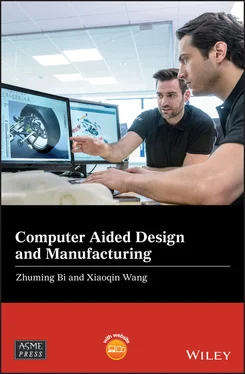
Zhuming Bi - Computer Aided Design and Manufacturing

Здесь есть возможность читать онлайн «Zhuming Bi - Computer Aided Design and Manufacturing» — ознакомительный отрывок электронной книги совершенно бесплатно, а после прочтения отрывка купить полную версию. В некоторых случаях можно слушать аудио, скачать через торрент в формате fb2 и присутствует краткое содержание. Жанр: unrecognised, на английском языке. Описание произведения, (предисловие) а так же отзывы посетителей доступны на портале библиотеки ЛибКат.

Computer Aided Design and Manufacturing: краткое содержание, описание и аннотация

Предлагаем к чтению аннотацию, описание, краткое содержание или предисловие (зависит от того, что написал сам автор книги «Computer Aided Design and Manufacturing»). Если вы не нашли необходимую информацию о книге — напишите в комментариях, мы постараемся отыскать её.

Broad coverage of digital product creation, from design to manufacture and process optimization This book addresses the need to provide up-to-date coverage of current CAD/CAM usage and implementation. It covers, in one source, the entire design-to-manufacture process, reflecting the industry trend to further integrate CAD and CAM into a single, unified process. It also updates the computer aided design theory and methods in modern manufacturing systems and examines the most advanced computer-aided tools used in digital manufacturing.
Computer Aided Design and Manufacturing being uniquely structured to classify and align engineering disciplines and computer aided technologies from the perspective of the design needs in whole product life cycles, utilizing a comprehensive Solidworks package (add-ins, toolbox, and library) to showcase the most critical functionalities of modern computer aided tools, and presenting real-world design projects and case studies so that readers can gain CAD and CAM problem-solving skills upon the CAD/CAM theory.
is an ideal textbook for undergraduate and graduate students in mechanical engineering, manufacturing engineering, and industrial engineering. It can also be used as a technical reference for researchers and engineers in mechanical and manufacturing engineering or computer-aided technologies.
Computer Aided Design and Manufacturing — читать онлайн ознакомительный отрывок

Ниже представлен текст книги, разбитый по страницам. Система сохранения места последней прочитанной страницы, позволяет с удобством читать онлайн бесплатно книгу «Computer Aided Design and Manufacturing», без необходимости каждый раз заново искать на чём Вы остановились. Поставьте закладку, и сможете в любой момент перейти на страницу, на которой закончили чтение.

Тёмная тема
Сбросить

Интервал:

Закладка:

Сделать

3 Chapter 3 Figure 3.1 Engineering design process. Figure 3.2 Morphological and topological level of geometric automation. Figure 3.3 Widely used knowledge‐based engineering (KBE) tools. Figure 3.4 Hierarchical computer model from parametric modelling. Figure 3.5 Knowledge‐based engineering (KBE) for parametric modelling. Figure 3.6 Point and its coordinates in three‐dimensional space. Figure 3.7 Define a line and its parameters. Figure 3.8 Define a plane and its parameters. Figure 3.9 Define a 2D curve and its parameters in SolidWorks. Figure 3.10 Define a 3D curve and its parameters in SolidWorks. Figure 3.11 Types of parameters. Figure 3.12 Examples of different types of parameters. (a) Parameters for dime...Figure 3.13 Intrinsic parameters and user parameters. (a) User parameters. (b)...Figure 3.14 Defining a dimensional parameter by ‘smart dimension’ in SolidWork...Figure 3.15 Types of geometric constraints in sketches. (a) Perpendicular. (b)...Figure 3.16 Define the relations in a sketch. (a) Activating ‘Display/Delete R...Figure 3.17 Selection of a default location of part as a design intent.Figure 3.18 Selection of first sketch plane as a design intent.Figure 3.19 Dependent variables in threads. (a) Thread. (b) Detailed view of d...Figure 3.20 Creating design equations in SolidWorks. (a) Access ‘equations’ to...Figure 3.21 Design equations in a Lego piece model (unit: mm). (a) Male surfac...Figure 3.22 Three common ways of innovations and creations. (a) Copying. (b) T...Figure 3.23 Examples of using a design table for part families. (a) Springs. (...Figure 3.24 Examples of using a design table for assemblies. (a) Valves. (b) C...Figure 3.25 Creating configurations in a design table. (a) Manually created co...Figure 3.26 Procedure for creating a part model with a design table.Figure 3.27 Defining a design table in SolidWorks. (a) Insert a design table. ...Figure 3.28 Example of creating a part model with a design table. (a) Define c...Figure 3.29 Example of creating a part model with a design table.Figure 3.30 Example of using design equations in a design table in SolidWorks.Figure 3.31 Example of using the concatenation function to create part numbers...Figure 3.32 Activate ‘Configuration Publisher’ tool in SolidWorks.Figure 3.33 Showing a list of the properties for filtering.Figure 3.34 Specify a configuration with a configuration publisher in an assem...Figure 3.35 Example of an assembly model with the variants from a part level. ...Figure 3.36 Design table at an assembly model.Figure 3.37 Design table at a part model.Figure 3.38 The product variants at the Rotomation Inc. (Rotomation 2019). (a)...Figure 3.39 Templates for part, assembly, and drawing models in SolidWorks.Figure 3.40 Template for static analysis in SolidWorks.Figure 3.41 Drawing family A.Figure 3.42 Drawing family B.Figure 3.43 Part A.Figure 3.44 Part B.Figure 3.45 Example cell phone cover family.Figure 3.46 Example car snow scraper family.

4 Chapter 4Figure 4.1 Aircraft design when one group is dominant (Mason 2009; Nicolai and...Figure 4.2 Committed cost of product over its lifecycle.Figure 4.3 Example of cost reduction by CE (Heizer and Render 2008).Figure 4.4 Challenges in CE practice (Nadadur et al. 2012).Figure 4.5 CE and Continuous Improvement (CI) in the product design cycle.Figure 4.6 Examples of product platforms. (a) Robotic tool changers. (b) Indus...Figure 4.7 Relevant terminologies of platform technologies.Figure 4.8 Needs of modularization by example of a complex product (Airbus 201...Figure 4.9 Universal motors by Black & Decker using a bottom‐up method (Simpso...Figure 4.10 Platforms of Walkman products at Sony Inc. (Sanderson and Uzumeri ...Figure 4.11 Evolution of product platforms at Volkswagen (Johnson 2013; Kreind...Figure 4.12 Example of using the platform technologies for the cost reduction ...Figure 4.13 Platform technologies for cost savings.Figure 4.14 Overview of platform‐based product family design methods (Zha and ...Figure 4.15 Types of modules in a product platform.Figure 4.16 Prioritizing commonalities for different module types.Figure 4.17 Configure product variants from a product platform. (a) A + B + C(...Figure 4.18 Ford auto platform with subsystems and interfaces (Simpson 2019).Figure 4.19 Modularization of a product family.Figure 4.20 Zigzagging decomposition in axiomatic design theory (ADT). (a) Map...Figure 4.21 Structure of module‐based product platform (Golfmann and Lammers 2...Figure 4.22 Example of decomposition of Functional Requirements (FRs).Figure 4.23 Braun coffee maker families (Simpson 2019).Figure 4.24 The Boeing 737 family (Wikiwand 2019).Figure 4.25 Traditional product design method without consideration of product...Figure 4.26 Top‐down approach.Figure 4.27 Bottom‐up approach.Figure 4.28 Traditional static product structure with no leveraging.Figure 4.29 Horizontal leveraging product platforms.Figure 4.30 Horizontally leveraged B&D power platforms (MIT 2019).Figure 4.31 Vertical leveraging product platforms.Figure 4.32 Vertically leveraged Gillette shaver platforms (MIT 2019).Figure 4.33 Beachhead leveraging product platforms.Figure 4.34 Beachhead leveraged ice scraper platforms (MIT 2019).Figure 4.35 Modular robot systems.Figure 4.36 Design variables in modular robot platform based on ADT.Figure 4.37 The DH notation for spatial relations of two motion axes.Figure 4.38 Robot platform design I. (a) Rotary joint (0.07 × 0.07 × 0.14) ass...Figure 4.39 Robot platform design II. (a) Rotary joint (0.07 × 0.07 × 0.07). (...Figure 4.40 Robot platform design III. (a) Rotational joint assembly patterns:...Figure 4.41 Product platform techniques for standardization and reusability.Figure 4.42 Difference of morphological and topological changes. (a) Original ...Figure 4.43 Example of rotary actuator with many standardized parts or feature...Figure 4.44 Creating a feature, part, component, or configuration in a design ...Figure 4.45Figure 4.45 Example of gearbox models for design project 1.Figure 4.46Figure 4.46 Example of creating a custom design library for knowle...

5 Chapter 5Figure 5.1 Forward engineering (FE) and reverse engineering (RE).Figure 5.2 Part‐to‐CAD and CAD‐to‐part processes in RE. (a) Clay model. (b) Sc...Figure 5.3 Correspondence of manipulator and human body. (a) Human being. (b) ...Figure 5.4 Example of inventions inspired by nature (Hennighausen and Roston 2...Figure 5.5 Digital modelling and re‐conception process in RE (Bernard et al. 2...Figure 5.6 Example of reverse engineering at different levels.Figure 5.7 Three phases of RE. (a) The first phase to create point cloud or po...Figure 5.8 Three types of point clouds (Chen et al. 2018). (a) Unorganized. (b...Figure 5.9 Steps in creating a parametric surface from a point cloud (Creaform...Figure 5.10 Critical tasks from data acquisition to reconstructed surface/mode...Figure 5.11 The procedure of surface reconstruction.Figure 5.12 A data point and its weights on the neighbouring nodes.Figure 5.13 Special cases of contouring tracking (Wikipedia 2019b).Figure 5.14 Classification of hardware systems for data acquisition.Figure 5.15 Examples of destructive and contact devices. (a) Destructive scann...Figure 5.16 Meshed points from a contact device. (a) Physical object. (b) Mesh...Figure 5.17 Examples of active data acquisition systems. (a) Transmissive sens...Figure 5.18 Single‐point and line scanning methods (Boehler et al. 2002). (a) ...Figure 5.19 Using the time‐of‐flight concept to calculate distance.Figure 5.20 Example of the time‐of‐flight laser sensor (Sick 2019).Figure 5.21 An image example acquired by an interferometry sensor (www.capture...Figure 5.22 The idea of photogrammetry (Rajia and Fernandes 2008).Figure 5.23 Comparison of 3D scanning and camera for photogrammetry.Figure 5.24 Positioning methods in scanning. (a) Mechanical encoding. (b) Trac...Figure 5.25 Scanning paths and sensor types. (a) Single‐point scanning: ...Figure 5.26 Procedure and design factors in an automated CRP (Barnes et al. 20...Figure 5.27 Commercial and open‐source software tools for RE.Figure 5.28 Cloud‐service for an RE project by Autodesk Recap Pro. (a) Launchi...Figure 5.29 The steps of using Recap Pro for an RE project. (1) Capture suffic...Figure 5.30 Processing and exporting a polygonal model in Recap Pro. (a) Editi...Figure 5.31 Procedure of generating a parametrized solid model by ScanTo3D by ...Figure 5.32 Divide and conquer an assembled product in reverse engineering (Go...Figure 5.33 Examples of sequential operations after digital modelling in RE (G...Figure 5.34 Example of a CARE design project.

Читать дальше
Тёмная тема
Сбросить

Интервал:

Закладка:

Сделать

Похожие книги на «Computer Aided Design and Manufacturing»

Представляем Вашему вниманию похожие книги на «Computer Aided Design and Manufacturing» списком для выбора. Мы отобрали схожую по названию и смыслу литературу в надежде предоставить читателям больше вариантов отыскать новые, интересные, ещё непрочитанные произведения.


Отзывы о книге «Computer Aided Design and Manufacturing»

Обсуждение, отзывы о книге «Computer Aided Design and Manufacturing» и просто собственные мнения читателей. Оставьте ваши комментарии, напишите, что Вы думаете о произведении, его смысле или главных героях. Укажите что конкретно понравилось, а что нет, и почему Вы так считаете.

x