Mohinder S. Grewal - Global Navigation Satellite Systems, Inertial Navigation, and Integration
Здесь есть возможность читать онлайн «Mohinder S. Grewal - Global Navigation Satellite Systems, Inertial Navigation, and Integration» — ознакомительный отрывок электронной книги совершенно бесплатно, а после прочтения отрывка купить полную версию. В некоторых случаях можно слушать аудио, скачать через торрент в формате fb2 и присутствует краткое содержание. Жанр: unrecognised, на английском языке. Описание произведения, (предисловие) а так же отзывы посетителей доступны на портале библиотеки ЛибКат.
- Название:Global Navigation Satellite Systems, Inertial Navigation, and Integration
- Автор:
- Жанр:
- Год:неизвестен
- ISBN:нет данных
- Рейтинг книги:4 / 5. Голосов: 1
-
Избранное:Добавить в избранное
- Отзывы:
-
Ваша оценка:
Global Navigation Satellite Systems, Inertial Navigation, and Integration: краткое содержание, описание и аннотация
Предлагаем к чтению аннотацию, описание, краткое содержание или предисловие (зависит от того, что написал сам автор книги «Global Navigation Satellite Systems, Inertial Navigation, and Integration»). Если вы не нашли необходимую информацию о книге — напишите в комментариях, мы постараемся отыскать её.
GNSSs including GPS, Glonass, Galileo, BeiDou, QZSS, and IRNSS/NAViC,
and MATLAB programs on square root information filtering (SRIF)
This book provides readers with solutions to real-world problems associated with global navigation satellite systems, inertial navigation, and integration. It presents readers with numerous detailed examples and practice problems, including GNSS-aided INS, modeling of gyros and accelerometers, and SBAS and GBAS. This revised fourth edition adds new material on GPS III and RAIM. It also provides updated information on low cost sensors such as MEMS, as well as GLONASS, Galileo, BeiDou, QZSS, and IRNSS/NAViC, and QZSS. Revisions also include added material on the more numerically stable square-root information filter (SRIF) with MATLAB programs and examples from GNSS system state filters such as ensemble time filter with square-root covariance filter (SRCF) of Bierman and Thornton and SigmaRho filter.
Global Navigation Satellite Systems, Inertial Navigation, and Integration, 4th Edition Updates on the significant upgrades in existing GNSS systems, and on other systems currently under advanced development Expanded coverage of basic principles of antenna design, and practical antenna design solutions More information on basic principles of receiver design, and an update of the foundations for code and carrier acquisition and tracking within a GNSS receiver Examples demonstrating independence of Kalman filtering from probability density functions of error sources beyond their means and covariances New coverage of inertial navigation to cover recent technology developments and the mathematical models and methods used in its implementation Wider coverage of GNSS/INS integration, including derivation of a unified GNSS/INS integration model, its MATLAB implementations, and performance evaluation under simulated dynamic conditions
is intended for people who need a working knowledge of Global Navigation Satellite Systems (GNSS), Inertial Navigation Systems (INS), and the Kalman filtering models and methods used in their integration.
Global Navigation Satellite Systems, Inertial Navigation, and Integration — читать онлайн ознакомительный отрывок
Ниже представлен текст книги, разбитый по страницам. Система сохранения места последней прочитанной страницы, позволяет с удобством читать онлайн бесплатно книгу «Global Navigation Satellite Systems, Inertial Navigation, and Integration», без необходимости каждый раз заново искать на чём Вы остановились. Поставьте закладку, и сможете в любой момент перейти на страницу, на которой закончили чтение.
Интервал:
Закладка:
Navigation functions that are not shown in Figure 3.21include:
1 How initialization of the integrals for position, velocity, and attitude is implemented. Initial position and velocity can be input from other sources (GNSS, for example), and attitude can be inferred from some form of trajectory matching (using GPS, for example) or by gyrocompassing.
2 How attitude rates are integrated to obtain attitude, described in Section 3.6.1.1.
3 For the case that navigation coordinates are Earth‐fixed, the computation of navigational coordinate rotation due to earthrate as a function of position, and its summation with sensed rates before integration.
4 For the case that navigation coordinates are locally‐level, the computation includes the rotation rate of navigation coordinates due to vehicle horizontal velocity and its summation with sensed rates before integration.
5 Calibration of the sensors for error compensation. If the errors are sufficiently stable, it needs to be done only once. Otherwise, it can be implemented using the GNSS/INS integration techniques discussed in Chapter 12.
Figure 3.22is a process flow diagram for the same implementation, arranged such that the variables available for other functions is around the periphery. These are the sorts of variables that might be needed for driving cockpit displays, antennas, weaponry, sensors, or other surveillance assets.
3.6.2.3 Gimbaled Navigation Propagation
The signal flowchart in Figure 3.23shows the essential navigation signal processing functions for a gimbaled INS with inertial sensor axes aligned to locally level coordinates, where
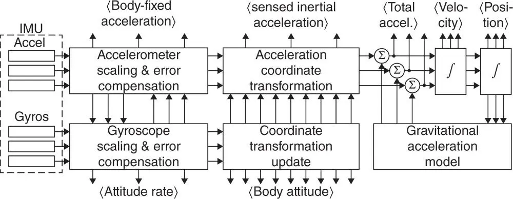
Figure 3.22Outputs (in angular brackets) of simple strapdown INS.
is the specific force (i.e. the sensible acceleration, which does not include gravitational acceleration) applied to the host vehicle.
is the instantaneous inertial rotation rate vector of the host vehicle.
denotes a specific force sensor (accelerometer).
denotes the ensemble of gimbal angle encoders, one for each gimbal angle. There are several possible formats for the gimbal angles, including digitized angles, three‐wire synchros signals, or pairs.
denotes an inertial rotation sensor (gyroscope).
Position is the estimated position of the host vehicle in navigation coordinates (e.g. longitude, latitude, and altitude relative to sea level).
Velocity is the estimated velocity of the host vehicle in navigation coordinates (e.g. east, north, and vertical).
Attitude is the estimated attitude of the host vehicle relative to locally level coordinates. For some three‐gimbal systems, the gimbal angles are the Euler angles representing vehicle heading (with respect to north), pitch (with respect to horizontal), and roll. Output attitude may also be used to drive cockpit displays such as compass cards or artificial horizon indicators.
Accelerometer Error Compensation and Gyroscope Error Compensation denote the calibrated corrections for sensor errors. These generally include corrections for scale factor variations, output biases, and input axis misalignments for both types of sensors, and acceleration‐dependent errors for gyroscopes.
Gravity denotes the gravity model used to compute the acceleration due to gravity as a function of position.
Coriolis denotes the acceleration correction for Coriolis effect in rotating coordinates.
Leveling denotes the rotation rate correction to maintain locally level coordinates while moving over the surface of the Earth.
Earth Rate denotes the model used to calculate the Earth rotation rate in locally level INS coordinates.
Torquing denotes the servo loop gain computations used in stabilizing the INS in locally level coordinates.
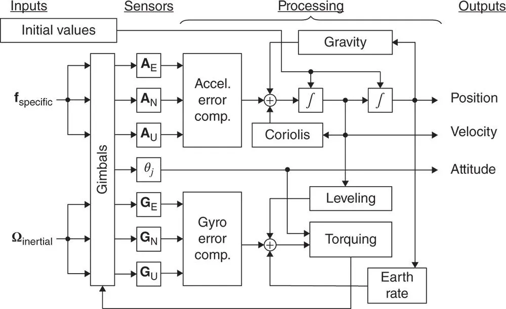
Figure 3.23Essential navigation signal processing for gimbaled INS.
Not shown in the figure is the input altitude reference (e.g. barometric altimeter or GNSS) required for vertical channel (altitude) stabilization.
3.7 Testing and Evaluation
The final stage of the development cycle is testing and performance evaluation. For standalone inertial systems, this usually proceeds from the laboratory to a succession of host vehicles, depending on the application.
3.7.1 Laboratory Testing
Laboratory testing is used to evaluate sensors before and after their installation in the ISA, and then to evaluate the system implementation during operation. The navigation solution from a stationary system should remain stationary, and any deviation is due to navigation errors. Testing with the system stationary can also be used to verify that position errors due to intentional initial velocity errors follow a path predicted by Schuler oscillations (  ‐minute period, described in Chapter 11) and the Coriolis effect. If not, there is an implementation error. Other laboratory testing may include controlled tilts and rotations to verify the attitude estimation implementations, and detect any un‐compensated sensitivities to rotation and acceleration.
Additional laboratory testing may be required for specific applications. Systems designed to operate aboard Navy ships, for example, may be required to meet their performance requirements under dynamic disturbances at least as bad as those to be expected aboard ships under the worst sea conditions. This may include what is known as a “Scoresby test,” used at the US Naval Observatory in the early twentieth century for testing gyrocompasses. Test conditions may include roll angles of  and pitch angles of
  , at varying periods in the order of a second.
Drop tests (for handling verification) and shake‐table or centrifuge tests (for assessing acceleration capabilities) can also be done in the laboratory.
3.7.2 Field Testing
After laboratory testing, systems are commonly evaluated next in highway testing.
Systems designed for tactical aircraft must be designed to meet their performance specifications under the expected peak dynamic loading, which is generally determined by the pilot's limitations.
Systems designed for rockets must be tested under conditions expected during launch, sometimes as a “piggyback” payload during the launch of a rocket for another purpose. Accelerations can reach around  for manned launch vehicles, and much higher for unmanned launch vehicles.
In all cases, GNSS has become an important part of field instrumentation. The Central Inertial Guidance Test Facility at Holoman AFB was once equipped with elaborate range instrumentation for this purpose, which is now performed at much lower cost using GNSS.
3.7.3 Performance Qualification Testing
The essential performance metric for any navigation system is accuracy, commonly specified in terms of position accuracy. However, because inertial navigation also provides attitude and velocity information, those may also be factors in performance assessments. In the case of integrated GNSS/INS systems, there may be an additional performance metric related to how fast navigational accuracy degrades when GNSS signal reception is lost. INS‐only navigation is called free inertia navigation , and we will start there. Integrated GNSS/INS performance is addressed in Chapter 12.
Читать дальшеИнтервал:
Закладка:
Похожие книги на «Global Navigation Satellite Systems, Inertial Navigation, and Integration»
Представляем Вашему вниманию похожие книги на «Global Navigation Satellite Systems, Inertial Navigation, and Integration» списком для выбора. Мы отобрали схожую по названию и смыслу литературу в надежде предоставить читателям больше вариантов отыскать новые, интересные, ещё непрочитанные произведения.


Обсуждение, отзывы о книге «Global Navigation Satellite Systems, Inertial Navigation, and Integration» и просто собственные мнения читателей. Оставьте ваши комментарии, напишите, что Вы думаете о произведении, его смысле или главных героях. Укажите что конкретно понравилось, а что нет, и почему Вы так считаете.