Anthony Kelly - Crystallography and Crystal Defects
Здесь есть возможность читать онлайн «Anthony Kelly - Crystallography and Crystal Defects» — ознакомительный отрывок электронной книги совершенно бесплатно, а после прочтения отрывка купить полную версию. В некоторых случаях можно слушать аудио, скачать через торрент в формате fb2 и присутствует краткое содержание. Жанр: unrecognised, на английском языке. Описание произведения, (предисловие) а так же отзывы посетителей доступны на портале библиотеки ЛибКат.
- Название:Crystallography and Crystal Defects
- Автор:
- Жанр:
- Год:неизвестен
- ISBN:нет данных
- Рейтинг книги:3 / 5. Голосов: 1
-
Избранное:Добавить в избранное
- Отзывы:
-
Ваша оценка:
Crystallography and Crystal Defects: краткое содержание, описание и аннотация
Предлагаем к чтению аннотацию, описание, краткое содержание или предисловие (зависит от того, что написал сам автор книги «Crystallography and Crystal Defects»). Если вы не нашли необходимую информацию о книге — напишите в комментариях, мы постараемся отыскать её.
explains the modern concepts of crystallography in a clear, succinct manner and shows how to apply these concepts in the analyses of point, line and planar defects in crystalline materials.
Fully revised and updated, this book now includes:
Original source references to key crystallographic terms familiar to materials scientists Expanded discussion on the elasticity of cubic materials New content on texture that contains more detail on Euler angles, orientation distribution functions and an expanded discussion on examples of textures in engineering materials Additional content on dislocations in materials of symmetry lower than cubic An expanded discussion of twinning which includes the description and classification of growth twins The inclusion and explanation of results from atomistic modelling of twin boundaries Problem sets with new questions, detailed worked solutions, supplementary lecture material and online computer programs for crystallographic calculations. Written by authors with extensive lecturing experience at undergraduate level,
continues to take its place as the core text on the topic and provides the essential resource for students and researchers in metallurgy, materials science, physics, chemistry, electrical, civil and mechanical engineering.
Crystallography and Crystal Defects — читать онлайн ознакомительный отрывок
Ниже представлен текст книги, разбитый по страницам. Система сохранения места последней прочитанной страницы, позволяет с удобством читать онлайн бесплатно книгу «Crystallography and Crystal Defects», без необходимости каждый раз заново искать на чём Вы остановились. Поставьте закладку, и сможете в любой момент перейти на страницу, на которой закончили чтение.
Интервал:
Закладка:
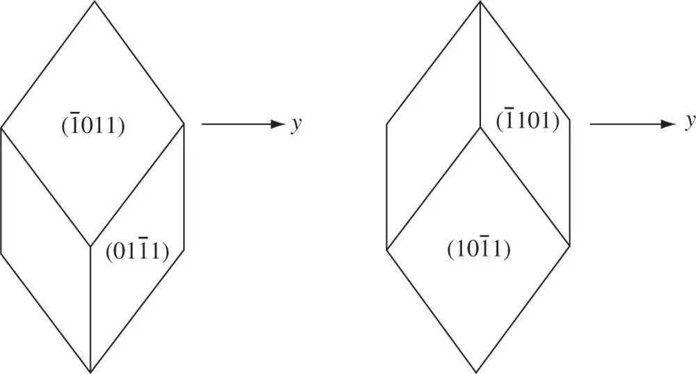
Figure 2.18The relationship between the special forms {10  1} and {01
  1} in the trigonal system
The other trigonal point groups are shown in Figure 2.6. In 3 and in  there are neither mirrors nor diads. The class 3 m has three mirrors intersecting in the triad axis; the x ‐, y ‐ and u ‐axes of the hexagonal cell are taken to lie perpendicular to the mirror planes. The point group 32 contains diads normal to 3 (consistent with the geometry for permissible combinations of rotational symmetry operations in Table 1.2), which are taken as the crystallographic axes. If three mirror planes intersect in an inversion triad, as in
  m , then diads automatically arise normal to the mirror planes; the diads are chosen as the x ‐, y ‐ and u ‐axes. Finally, we note that the class 3/ m is not specified as a point group in the trigonal system: it is placed in the hexagonal system because it is equivalent to
  .
.
2.7 Monoclinic System
Crystals in the monoclinic system possess a single twofold axis. Since a mirror plane is equivalent to an inverse diad, the class m (≡  ) is put into this system. Two settings are shown in Figure 2.6for the monoclinic point groups, depending on whether the stereogram is centred on the twofold axis (the 1st setting) or whether the twofold axis is lying in the equatorial plane of the stereogram (the 2nd setting).
With respect to the convention for choosing x ‐, y ‐ and z ‐axes for stereograms centred on the normal to the 001 planes for orthorhombic, tetragonal, and cubic crystals, the twofold axis is along the z ‐axis in the 1st setting, so that the angle γ between the x ‐ and y ‐axes is obtuse (as for hexagonal crystals, where γ is fixed to be 120°), while α = β = 90°. In the 2nd setting, the twofold axis is along the y ‐axis, so that the angle β between the x ‐ and z ‐axes is obtuse, while α = γ = 90°. Somewhat confusingly, both conventions are used in the scientific literature to describe the unit cells of monoclinic crystals, but it is much more common in materials science and metallurgy for the 2nd setting to be used, as we have chosen to do in Table 1.3 and Figures 1.19b and c. Irrespective of the choice of 1st or 2nd setting, the sides of the unit cells of crystals belonging to the monoclinic system are in general all unequal to one another.
The symmetry elements in the holosymmetric point group 2/ m are shown in Figure 2.19for the 2nd setting. The pole of (010) and the y ‐axis coincide on the stereogram. In this figure, [001], the z ‐axis, is chosen to be at the centre of the primitive and so (100) lies on the primitive 90° from (010). The x ‐axis, the direction [100], which makes the obtuse angle β with [001], is necessarily in the lower hemisphere. The angle between [001] and (001) is ( β − 90°), which is of course equal to the angle between the (100) pole and [100]. Poles such as { hk 0} lie around the primitive because [001] lies in { hk 0} planes (Weiss zone law, Eq. (1.6)).
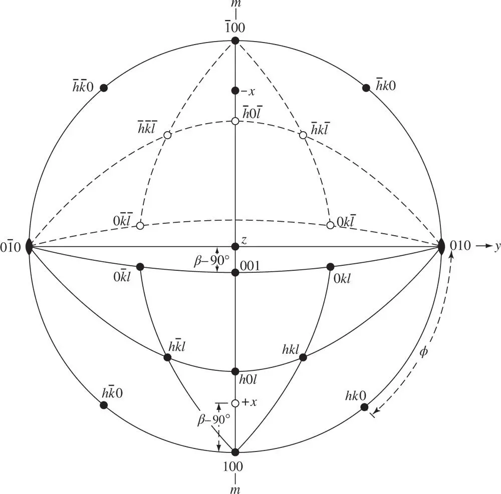
Figure 2.19Monoclinic stereogram centred on [001] for the 2nd setting
A pole such as ( hk 0) lies at angle ϕ to (010), given by:
(2.9a) 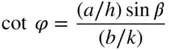
(see Figure 2.20), or equivalently (Section A3.2):
(2.9b) 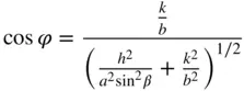
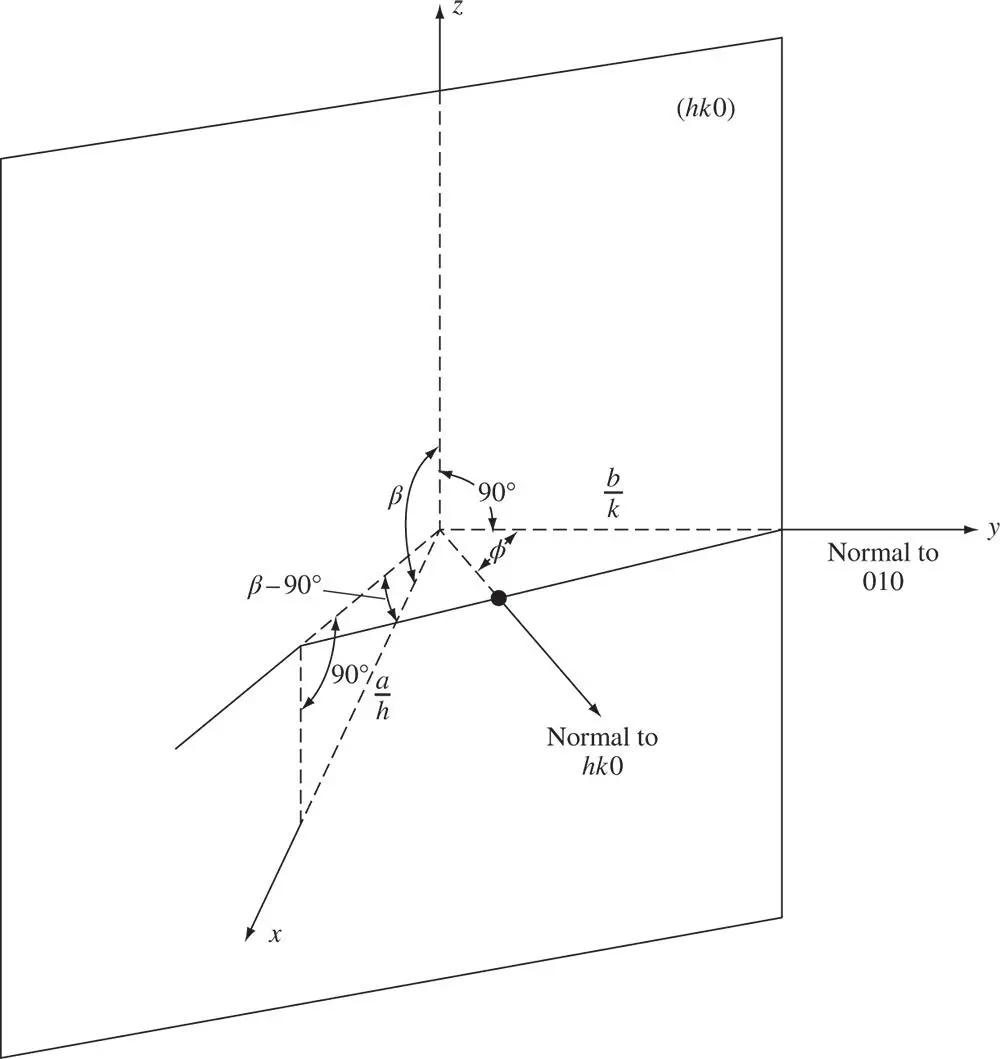
Figure 2.20A diagram from which the angle φ in Figure 2.19between 010 and hk 0 can be derived
The factor sin β arises because the x ‐axis does not lie in the same plane as the plane perpendicular to the z ‐axis within which the normals to ( hk 0) and (010) both lie. In the point group 2/ m the only special form besides {010} is { h 0 l }, with a multiplicity of two – the planes ( h 0 l ) and (  0
0  ). It is apparent that the two faces in this latter form are parallel, both lying normal to the mirror plane and parallel to the diad axis. The general form is { hkl }, with a multiplicity of four (see Figure 2.19). { hk 0} and {0 kl } are also general forms.
The remaining point groups in the monoclinic system are 2 and m . Again, { h 0 l } is a special form in both and so is {010}. However, 2 does not possess a centre, and so for this point group {010} and {0  0} must each be listed as separate special forms.
2.8 Triclinic System
There are no special forms in either of the point groups in this system. The unit cell is a general parallelepiped and the geometry is more complicated than even for the monoclinic system. The drawing of a stereogram whose centre is taken to be the z ‐axis, [001], can be carried out with the aid of Figures 2.21a and b. The two diagrams here are completely general and can be specialized to apply to any crystal system more symmetric than the triclinic by setting one or more of the axial angles to particular values and by setting two or more of the lattice parameters to be equal.
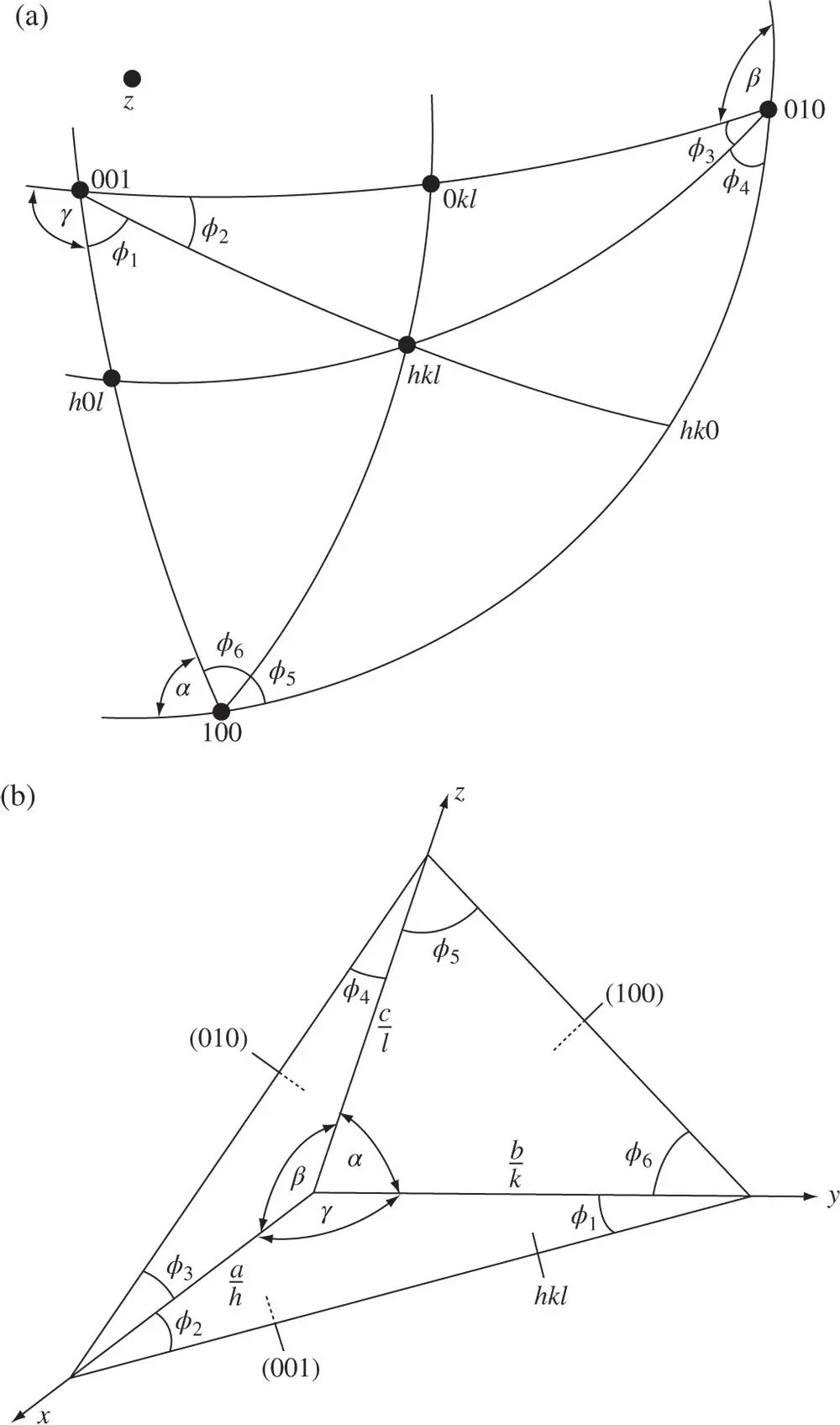
Figure 2.21Diagrams relevant to drawing stereograms of triclinic crystals. The centre of the stereogram in (a) is the z ‐axis, [001]
The choice of the centre of the stereogram as the z ‐axis in Figure 2.21a means that all planes of the general form ( hk 0) lie on the primitive of the stereogram, just as for the monoclinic stereogram in Figure 2.19. However, for triclinic crystals there is no good reason to have the 010 pole located on the right‐hand side of the horizontal axis of the stereogram, and so here it is deliberately rotated around the primitive away from this position.
Читать дальшеИнтервал:
Закладка:
Похожие книги на «Crystallography and Crystal Defects»
Представляем Вашему вниманию похожие книги на «Crystallography and Crystal Defects» списком для выбора. Мы отобрали схожую по названию и смыслу литературу в надежде предоставить читателям больше вариантов отыскать новые, интересные, ещё непрочитанные произведения.


Обсуждение, отзывы о книге «Crystallography and Crystal Defects» и просто собственные мнения читателей. Оставьте ваши комментарии, напишите, что Вы думаете о произведении, его смысле или главных героях. Укажите что конкретно понравилось, а что нет, и почему Вы так считаете.