Joel P. Dunsmore - Handbook of Microwave Component Measurements
Здесь есть возможность читать онлайн «Joel P. Dunsmore - Handbook of Microwave Component Measurements» — ознакомительный отрывок электронной книги совершенно бесплатно, а после прочтения отрывка купить полную версию. В некоторых случаях можно слушать аудио, скачать через торрент в формате fb2 и присутствует краткое содержание. Жанр: unrecognised, на английском языке. Описание произведения, (предисловие) а так же отзывы посетителей доступны на портале библиотеки ЛибКат.

- Название:Handbook of Microwave Component Measurements
- Автор:
- Жанр:
- Год:неизвестен
- ISBN:нет данных
- Рейтинг книги:5 / 5. Голосов: 1
-
Избранное:Добавить в избранное
- Отзывы:
-
Ваша оценка:
Handbook of Microwave Component Measurements: краткое содержание, описание и аннотация
Предлагаем к чтению аннотацию, описание, краткое содержание или предисловие (зависит от того, что написал сам автор книги «Handbook of Microwave Component Measurements»). Если вы не нашли необходимую информацию о книге — напишите в комментариях, мы постараемся отыскать её.
Handbook of Microwave Component Measurements — читать онлайн ознакомительный отрывок
Ниже представлен текст книги, разбитый по страницам. Система сохранения места последней прочитанной страницы, позволяет с удобством читать онлайн бесплатно книгу «Handbook of Microwave Component Measurements», без необходимости каждый раз заново искать на чём Вы остановились. Поставьте закладку, и сможете в любой момент перейти на страницу, на которой закончили чтение.
Интервал:
Закладка:
Mixers with baluns can suppress some of the higher‐order products, with baluns on the RF port suppressing products that have even‐order LO spurious, and baluns on the LO port suppressing products that have even‐order RF spurious. These are called single‐balance mixers , and it is typical that the LO port is balanced. Double‐balanced mixers have baluns on the RF or IF ports. Refer to Chapter 7for more details on mixer configurations. Triple‐balanced mixers are usually comprised of a pair of double‐balanced mixers, adding a balun to the IF port. Their main advantage is to divide the RF signal power between the two diode quads, lowering the RF relative to the LO, whereby the spurious signals created will be lower; then the outputs are combined to recover the power. This provides a mixer with the same conversion loss and lower spurious products at the same output power level. The disadvantage is that since the LO drive is also divided, higher LO drive power is needed to achieve the same linearity for each diode quad.
The creation of spurious mixer products is a key aspect of system design, with the goal of eliminating spurious signals from the IF output. Unfortunately, some frequency plans are such that the spurious products must fall into the band of interest. In such cases, system designers move to multiple conversion stages to create a first stage, which produces an output free of spurious signals over the range of input signals of interest, and then has a second conversion stage that produces the frequency of interest at the output. This multiple conversion or “dual‐LO” system is typically called a frequency converter and often contains additional filtering and amplification, as shown in Figure 1.41.
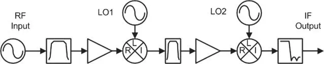
Figure 1.41 Dual‐LO frequency converter.
Because of the multiple components used, the frequency response of converters often has gain ripple and phase ripple, which can distort the information signal. Key figures of merit for converters are gain flatness, group delay flatness, and the related phase flatness, which is also known as deviation from linear phase, and represents residual ripple after fitting the phase data to a straight line. Modern systems employ equalization techniques that can remove some of the flatness effects provided they follow simple curvatures; as such, another specification found on converters is deviation from parabolic phase, which is the residual ripple in the phase data when it is fitted to a second order curve.
Mixers often have quite poor input or output match because of the switching nature of their operation, so their effect on system flatness when assembled into a converter can be quite dramatic. Until recently, it was difficult to predict the effects of output load of a mixer on its input match, but the mathematical tools to model mixers as system elements have been developed (Williams et al. 2005) that describe these relationships. Mixers that produce an output that is the sum of the input and output signals are relatively simple to describe, but mixers that produce an output that is the difference between input and LO have a more complicated behavior in the case where the input frequency is less the LO frequency. These are sometimes called image mixers , and their unusual characteristic is that as the input frequency goes up, the output frequency goes down; this also applies to phase: a negative phase shift of the input signal results in a positive phase shift of the output signal. How these special cases affect the system performance will be described in more precise mathematical terms in Chapter 7.
1.14.4 Frequency Multiplier and Limiters and Dividers
Mixers are not the only way to create new frequencies at the output; frequency multipliers are also used to generate high‐frequency signals, particularly when creating mm‐wave sources. Frequency multipliers produce harmonics by changing a sine‐wave input signal into non‐linear wave. The basic doubler is a half‐wave or full‐wave rectifier, such as a diode bridge. A pair of back‐to‐back diodes turns a sine wave into a square wave, which is rich in odd harmonic content. This is essentially the same as a limiter.
The key figure of merits of a multiplier is the conversion loss from fundamental drive to the desired harmonic. Other important characteristics are fundamental feed‐through and higher‐order harmonics.
Limiters have the key characteristic of maximum output power; that is the power at which they limit. Also important is the onset of limiting and the compression point. Ideal limiters are linear until the onset of limiting, and then they effectively clip the output voltage above that level.
Other multiplier types are step‐recovery diodes, and non‐linear transmission lines that, when driven with a sine wave, effectively “snap” on to produce a sharp edge. Depending upon the design, the on‐time can be short, which produces an output rich in harmonics. Some digital circuits can also be used to create narrow pulses from a sine‐wave input as a pulse generator. Such a pulse will also be rich in harmonics.
One aspect of a multiplier that is not easily discerned is the group delay through it. That is because for some change in input frequency one will see a multiplied change in output frequency. FM that passes through a doubler will have the same rate as the original FM, but twice the deviation. For this reason, doublers or multipliers are seldom used in the signal or communication path of RF or microwave systems but can be used in the base carrier paths and in the LOs of many systems.
1.14.4.1 Frequency Dividers
Frequency dividers provide for a lower value of frequency than the input frequency. Like multipliers they are highly non‐linear and often produce square‐wave outputs. Some key specifications of dividers are minimum and maximum input power to ensure proper operation of the divider, output power and harmonics, and additive phase noise. Typically, for each divide by two stage, the phase noise is reduced by 6 dB. But noise or jitter in the divide circuitry can add noise to the signal; the added phase noise at the output relative to the phase noise at the input is called additive phase noise . This is also a concern with mixers, where the LO phase noise can be added to the output signal, and to a lesser extent amplifiers.
1.14.5 Oscillators
Oscillators in some ways represent the most non‐linear of electrical circuits with frequencies created at the output with no input (other than noise). Oscillators have a wide variety of characteristics that are important to characterize, including output frequency, output power, harmonics, phase noise, frequency pushing (change in frequency with change in DC power), frequency pulling (change in frequency due to change in load impedance), and output match.
Voltage‐controlled oscillators (VCOs) have the additional ability to control the frequency of the output due to a voltage change at the input. The voltage‐to‐frequency control factor is a key attribute of a VCO. A related microwave component is a yttrium‐iron‐garnet (YIG) oscillator, which uses a spherical YIG resonator as the frequency control element of the YIG‐tuned‐oscillator (YTO). The YIG resonator has the characteristic that the resonant frequency changes with magnetic field. YTOs have wide tuning bandwidth (up to 10:1) and low phase noise. Tuning is performed by changing the current in an electromagnet but can be very low bandwidth due to the large inductance of the magnet. YTOs often have a second, lower inductance coil (called the FM coil ), which provides small change to frequency but with high bandwidth.
Читать дальшеИнтервал:
Закладка:
Похожие книги на «Handbook of Microwave Component Measurements»
Представляем Вашему вниманию похожие книги на «Handbook of Microwave Component Measurements» списком для выбора. Мы отобрали схожую по названию и смыслу литературу в надежде предоставить читателям больше вариантов отыскать новые, интересные, ещё непрочитанные произведения.


Обсуждение, отзывы о книге «Handbook of Microwave Component Measurements» и просто собственные мнения читателей. Оставьте ваши комментарии, напишите, что Вы думаете о произведении, его смысле или главных героях. Укажите что конкретно понравилось, а что нет, и почему Вы так считаете.