Joel P. Dunsmore - Handbook of Microwave Component Measurements
Здесь есть возможность читать онлайн «Joel P. Dunsmore - Handbook of Microwave Component Measurements» — ознакомительный отрывок электронной книги совершенно бесплатно, а после прочтения отрывка купить полную версию. В некоторых случаях можно слушать аудио, скачать через торрент в формате fb2 и присутствует краткое содержание. Жанр: unrecognised, на английском языке. Описание произведения, (предисловие) а так же отзывы посетителей доступны на портале библиотеки ЛибКат.

- Название:Handbook of Microwave Component Measurements
- Автор:
- Жанр:
- Год:неизвестен
- ISBN:нет данных
- Рейтинг книги:5 / 5. Голосов: 1
-
Избранное:Добавить в избранное
- Отзывы:
-
Ваша оценка:
Handbook of Microwave Component Measurements: краткое содержание, описание и аннотация
Предлагаем к чтению аннотацию, описание, краткое содержание или предисловие (зависит от того, что написал сам автор книги «Handbook of Microwave Component Measurements»). Если вы не нашли необходимую информацию о книге — напишите в комментариях, мы постараемся отыскать её.
Handbook of Microwave Component Measurements — читать онлайн ознакомительный отрывок
Ниже представлен текст книги, разбитый по страницам. Система сохранения места последней прочитанной страницы, позволяет с удобством читать онлайн бесплатно книгу «Handbook of Microwave Component Measurements», без необходимости каждый раз заново искать на чём Вы остановились. Поставьте закладку, и сможете в любой момент перейти на страницу, на которой закончили чтение.
Интервал:
Закладка:
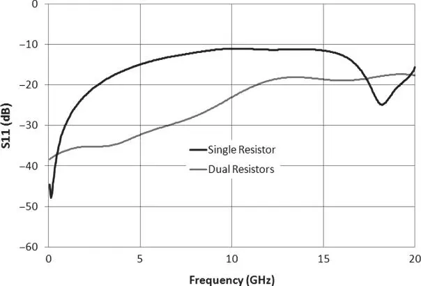
Figure 1.39 Input match of a single SMT resistor and two in parallel.
1.13.2 SMT Capacitors
SMT capacitors have a different model from resistors. To a first order, their parasitic effects tend to be all in series, as shown in the model of Figure 1.40. The series inductance is due to primarily to the package size and is similar to that of a resistor. The series resistance is due to the manufacturing characteristics of the capacitor and thus cannot be easily estimated. If an SMT capacitor is used in a resonant structure, this resistance will have the principal effect on the Q of the resonator. However, its effect is typically small in most wideband applications, where the capacitor is used as a series DC blocking capacitor or a shunt RF bypass capacitor. This is because the series inductance will dominate the series resistance in these use cases and cause the impedance of the capacitor to rise with frequency (rather than go to zero). At high frequencies, there may also exist a parasitic shunt capacitance across the entire package, which may cause the impedance to fall again.
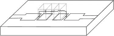
Figure 1.40 Model of an SMT capacitor.
The case where the series resistance is of consequence is when the capacitor is used in a turned circuit, where the package inductance may be subsumed in the resonating inductor and thus at resonance the series resistance adds to a degradation of the Q of the capacitor. With careful design, the capacitance value may be compensated for by the including the effects of the series inductance; this effect is to make the capacitor look larger than its prescribed value. In fact, where the reactance of the parasitic inductance equals the reactance of the capacitance, the effective value of capacitance goes to infinite and the series impedance becomes just the parasitic resistance. So, for characterizing capacitors for use in tuned circuits, one must really assess their value near the frequency on which they will be having the most effect on a circuit. Consider a one‐pole filter, where the cutoff of the filter starts to occur when the reactance of the capacitor reaches 50 Ω. In many cases, the inductance is quite significant and already altering the effective value of the capacitor. Thus, it is important to evaluate the effective capacitance near this point. A good rule of thumb is to evaluate a capacitor where the reactance is j50 Ω.
A further characteristic of capacitors that is significant is the internal assembly structure. Capacitors are typically formed by a set of interleaved parallel plates with alternate plates connected at each end to the terminals. The plates can be parallel to or vertical to the PC board. For some cases, the capacitor body itself can form a dielectric resonator at high frequency, but below that the capacitor can act as a single, large conductive block on a PC board trace, typically resulting in a model that might best be considered a transmission line of somewhat lower impedance than the mounting line.
Capacitors used as bypass capacitors have an additional parasitic effect from the series inductance of the ground via, and from the pad above the ground via.
1.13.3 SMT Inductors
Inductors are perhaps the most complicated of the simple passive components. Because they are constructed of coils of very fine wire, sometimes multiple layers of coils, their parasitic elements are greatly affected by the details of their construction. Some inductors have the axis of the coil parallel to the PC board, and some are wound with the axis perpendicular. In both cases, the model for the inductor is essentially the same as the resistor, as shown Figure 1.39, but with the value of the series inductance equal to the DC value of the inductor, and the series resistance equal to the DC resistance. Inductors, because of the nature of their construction, have very large relative parasitic capacitances. In cases where an inductor is used for a bias element (relying on its impedance to be high at high frequencies) one often finds that the parasitic capacitance will become the main effect over the band of interest. Thus, in many cases the value of inductance used is carefully selected based on the overall effective inductance and sometimes utilizes the shunt capacitance to provide a high impedance at a particular frequency of interest. It may quite difficult to make a single inductor provide good RF performance over a wide band.
When inductors are used as elements in filters, the parasitic capacitance can often have significant effects for use in band‐pass filters, and the inductance must be evaluated for each use to find the effective value considering the parasitic capacitance.
A common figure of merit for inductors is the self‐resonant frequency (SRF), above which they act more like a capacitor (impedance goes lower with increasing frequency) than an inductor. The value of the SRF can be estimated in one way by looking at the length of the wire used in making the inductor. The SRF will be less than the frequency for which the wire is one‐quarter wavelength.
1.13.4 PC Board Vias
The PC board via is perhaps the most common PC board component, and often the most overlooked. The effect of a via depends greatly upon how it is structured in the circuit. A single via to ground in the center of a transmission line appears as almost a pure inductance. However, a via between RF traces can have aspects of inductance and some parasitic capacitance (due to pads around the via) that can cancel, in part or all, the inductive effect. When a via is used in a mounting pad for a shunt element, such as a resistor used as a load, or a bypass capacitor, the mounting pad and via form a resonant structure such that the size of the mounting pad can increase the effective impedance of the via. Further, several vias are often used in parallel to ground devices, sometimes to lower their effective inductance and sometimes to provide greater heat sinking of an active device. Putting vias in parallel does lower their effective inductance, but not in a simple way. Rather than halving the inductance, mutual inductance between vias means that the value of effective inductance doesn't reduce as expected. For example, putting two 100 Ω resistors at the end of a line to ground, placed in parallel, may show much larger inductive effect the same two 100 Ω resistors place in a T pattern, where the ground vias are separated and the mutual inductance is less.
1.14 Active Microwave Components
With a few exceptions, passive components follow some fundamental rules that greatly simplify their characterization; principally, they are linear, so their characterization doesn't depend on the power of the signal used to characterize them, but only on the frequency. Active components, on the other hand, are sensitive to power, and their responses to both frequency stimulus and power stimulus are important. Often, passive components are operated well below any power level that causes a change in their response, but more and more active components are being driven into higher‐power operation to optimize their efficiency.
1.14.1 Linear and Non‐linear
In the measurement sense, one definition of linear devices is that they are devices in which the output power is a linear function of the input power. If the input power is doubled, the output power is doubled. Almost all passive devices follow this rule, and many active devices as well. An alternative definition of linear is one for which only frequencies that are available at the input appear at the output. In practice, the first definition is more useful for system response. Some important characteristics of active components are discussed next.
Читать дальшеИнтервал:
Закладка:
Похожие книги на «Handbook of Microwave Component Measurements»
Представляем Вашему вниманию похожие книги на «Handbook of Microwave Component Measurements» списком для выбора. Мы отобрали схожую по названию и смыслу литературу в надежде предоставить читателям больше вариантов отыскать новые, интересные, ещё непрочитанные произведения.


Обсуждение, отзывы о книге «Handbook of Microwave Component Measurements» и просто собственные мнения читателей. Оставьте ваши комментарии, напишите, что Вы думаете о произведении, его смысле или главных героях. Укажите что конкретно понравилось, а что нет, и почему Вы так считаете.