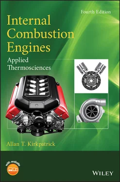
Allan T. Kirkpatrick - Internal Combustion Engines
Здесь есть возможность читать онлайн «Allan T. Kirkpatrick - Internal Combustion Engines» — ознакомительный отрывок электронной книги совершенно бесплатно, а после прочтения отрывка купить полную версию. В некоторых случаях можно слушать аудио, скачать через торрент в формате fb2 и присутствует краткое содержание. Жанр: unrecognised, на английском языке. Описание произведения, (предисловие) а так же отзывы посетителей доступны на портале библиотеки ЛибКат.
- Название:Internal Combustion Engines
- Автор:
- Жанр:
- Год:неизвестен
- ISBN:нет данных
- Рейтинг книги:5 / 5. Голосов: 1
-
Избранное:Добавить в избранное
- Отзывы:
-
Ваша оценка:
Internal Combustion Engines: краткое содержание, описание и аннотация
Предлагаем к чтению аннотацию, описание, краткое содержание или предисловие (зависит от того, что написал сам автор книги «Internal Combustion Engines»). Если вы не нашли необходимую информацию о книге — напишите в комментариях, мы постараемся отыскать её.
New engine technologies and concepts Effects of engine speed on performance and emissions Fluid mechanics of intake and exhaust flow in engines Turbocharger and supercharger performance analysis Chemical kinetic modeling, reaction mechanisms, and emissions Advanced combustion processes including low temperature combustion Piston, ring and journal bearing friction analysis The
expands on the combined analytical and numerical approaches used successfully in previous editions. Students and engineers are provided with several new tools for applying the fundamental principles of thermodynamics, fluid mechanics, and heat transfer to internal combustion engines.
Each chapter includes MATLAB programs and examples showing how to perform detailed engineering computations. The chapters also have an increased number of homework problems with which the reader can gauge their progress and retention. All the software is ‘open source’ so that readers can see in detail how computational analysis and the design of engines is performed. A companion website is also provided, offering access to the MATLAB computer programs.
 ,
,  ). Figure 2.2 Otto cycle thermal efficiency and imep as a function of compressi... Figure 2.3 The Diesel cycle (
  ,
,  ). Figure 2.4 Diesel cycle characteristics as a function of compression ratio a... Figure 2.5 The limited pressure cycle (
  ,
,  ). Figure 2.6 Comparison of limited pressure cycle with Otto and Diesel cycles ... Figure 2.7 The Miller cycle. Figure 2.8 Ratio of Miller to Otto cycle thermal efficiency with same compre... Figure 2.9 Ratio of Miller to Otto cycle imep with same compression ratio,
  Figure 2.10 Four‐stroke inlet and exhaust flow.
  inlet pressure,
  exhaust ... Figure 2.11 The exhaust stroke (4 to 5 to 6) illustrating residual mass. Figure 2.15 Cumulative mass fraction burned function. Figure 2.18 Dual Wiebe function for diesel energy release. (Adapted from Miy... Figure 2.21 Thermal efficiency vs. start of energy release for Examples 2.5 ... Figure 2.22 Imep vs. start of energy release for Examples 2.5 and 2.6. Figure 2.23 Cumulative work and heat/mass loss for Example 2.6.
 ); air mixtures for different... Figure 3.3 Equilibrium composition of octane (C 8H 18); air mixtures as a func... Figure 3.4 Specific heat
  of equilibrium combustion products versus tempera... Figure 3.5 Specific heat
  of equilibrium combustion products versus equival... Figure 3.6 Specific heat ratio
  of equilibrium combustion products versus e... Figure 3.7 Gas constant
  of equilibrium combustion products versus equivale... Figure 3.8 Enthalpy of combustion products for a gasoline–air mixture versus...Figure 3.9 Enthalpy of combustion products of a methanol–air mixture versus
 and the equilibrium heat of ...Figure 4.4 Effect of equivalence ratio on Otto fuel–air cycle.Figure 4.5 Effect of compression ratio on Otto fuel–air cycle.Figure 4.6 Effect of residual fraction on Otto fuel–air cycle.Figure 4.7 Effect of intake/exhaust pressure ratio on four‐stroke Otto fuel–...Figure 4.8 Effect of intake/exhaust pressure ratio on four‐stroke Otto fuel–...Figure 4.9 Effect of equivalence ratio on limited pressure fuel–air cycle.Figure 4.10 Effect of compression ratio on limited pressure fuel–air cycle....Figure 4.11 Energy release fraction versus crank angle (Example 4.8).Figure 4.12 Pressure versus crank angle (Example 4.8).Figure 4.13 Unburned and burned zone temperature versus crank angle (Example...Figure 4.14 Work and heat loss (J) versus crank angle (Example 4.8).Figure 4.15 Compression ignition energy release profile (Example 4.9).Figure 4.16 Compression ignition temperature versus crank angle (Example 4.9...Figure 4.17 Compression ignition pressure versus crank angle (Example 4.9)....Figure 4.18 Compression ignition cumulative work and heat loss versus crank ...Figure 4.19 Comparison of an actual spark ignition cycle with its equivalent...
 ) and geometric (
  ) valve cross‐section...Figure 5.4 Schematic of a steady flow bench.Figure 5.5 Effect of Reynolds number (Re =
  ) and nondimensional valve lift Figure 5.6 Flow patterns through an inlet valve. (Adapted from Annand and Ro...Figure 5.7 Valve discharge coefficient versus lift (Example 5.2).Figure 5.8 Valve flow coefficient versus lift (Example 5.2).Figure 5.9 Effect of valve lift on exhaust valve discharge coefficient. (Ada...Figure 5.10 Flow patterns through an exhaust valve. (Adapted from Annand and...Figure 5.11 Volumetric efficiency versus inlet valve Mach index in the regim...Figure 5.12 Valve diameter ratios for a flat cylinder head (b: bore, In: int...Figure 5.13 Representative exhaust and intake valve profiles.Figure 5.14 Conventional exhaust and intake valve profiles (Example 5.4).Figure 5.15 Cylinder pressure versus crank angle (Example 5.4).Figure 5.16 Inlet mass flow versus crank angle (Example 5.4).Figure 5.17 Exhaust mass flow versus crank angle (Example 5.4).Figure 5.18 Effect of valve timing on volumetric efficiency (Example 5.5).Figure 5.19 Inlet mass flow versus crank angle for conventional timing (Exam...Figure 5.20 Inlet mass flow versus crank angle for high performance timing (...Figure 5.21 Automotive engine intake manifold. (Courtesy Brodix, Inc.)Figure 5.22 Intake manifold pressure and frequency at low speed (
  rpm). (Ad...Figure 5.23 Intake manifold pressure and frequency at high speed (
  rpm). (A...Figure 5.24 Volumetric efficiency versus engine speed and intake runner leng...Figure 5.25 CFD grid for intake manifold flow. (Courtesy Adapco.)Figure 5.26 CFD velocity results for intake manifold flow. (Courtesy Adapco....Figure 5.27 CFD grid for exhaust manifold flow. (Courtesy Adapco.)Figure 5.28 CFD results for exhaust manifold flow. (Courtesy Adapco.)Figure 5.29 Two‐stroke scavenging configurations. (Adapted from Taylor 1985....Figure 5.30 Flow bench measurement of effective flow areas and discharge coe...Figure 5.31 Port discharge coefficient. (a) Variation with port opening at l...Figure 5.32 Crankcase and inlet pressure profiles for a two‐stroke motorcycl...Figure 5.33 Cylinder and exhaust pressure profiles for a two‐stroke motorcyc...Figure 5.34 Two‐stroke scavenging and trapping efficiencies.Figure 5.35 Two‐stroke scavenging efficiency versus engine speed. (Adapted f...Figure 5.36 Supercharger and turbocharger configurations.Figure 5.37 Comparison of turbine and compressor work.Figure 5.38 Types of positive displacement compressors.Figure 5.39 Turbocharger cutaway. (Courtesy PriceWeber.)Figure 5.40 Turbocharger cross‐section. (Adapted from Laustela et al. 1995.)...Figure 5.41 Centrifugal compressor cross‐section.Figure 5.42 Compressor enthalpy‐entropy diagram.Figure 5.43 Representative Roots supercharger performance. (Adapted from Sor...Figure 5.44 Centrifugal compressor map. The parameter
  is the Mach number b...Figure 5.45 Centrifugal compressor map. (Adapted from Anderson et al. 1984.)...Figure 5.46 Compressor impeller inlet and exit velocity triangles.Figure 5.47 Radial flow turbine cross‐section.Figure 5.48 Turbine enthalpy‐entropy diagram.Figure 5.49 Turbine rotor inlet and exit velocity triangles.Figure 5.50 Example plot of turbine efficiency versus blade speed ratio.