Position, Navigation, and Timing Technologies in the 21st Century
Здесь есть возможность читать онлайн «Position, Navigation, and Timing Technologies in the 21st Century» — ознакомительный отрывок электронной книги совершенно бесплатно, а после прочтения отрывка купить полную версию. В некоторых случаях можно слушать аудио, скачать через торрент в формате fb2 и присутствует краткое содержание. Жанр: unrecognised, на английском языке. Описание произведения, (предисловие) а так же отзывы посетителей доступны на портале библиотеки ЛибКат.

- Название:Position, Navigation, and Timing Technologies in the 21st Century
- Автор:
- Жанр:
- Год:неизвестен
- ISBN:нет данных
- Рейтинг книги:5 / 5. Голосов: 1
-
Избранное:Добавить в избранное
- Отзывы:
-
Ваша оценка:
Position, Navigation, and Timing Technologies in the 21st Century: краткое содержание, описание и аннотация
Предлагаем к чтению аннотацию, описание, краткое содержание или предисловие (зависит от того, что написал сам автор книги «Position, Navigation, and Timing Technologies in the 21st Century»). Если вы не нашли необходимую информацию о книге — напишите в комментариях, мы постараемся отыскать её.
Volume 1 of
contains three parts and focuses on the satellite navigation systems, technologies, and engineering and scientific applications. It starts with a historical perspective of GPS development and other related PNT development. Current global and regional navigation satellite systems (GNSS and RNSS), their inter-operability, signal quality monitoring, satellite orbit and time synchronization, and ground- and satellite-based augmentation systems are examined. Recent progresses in satellite navigation receiver technologies and challenges for operations in multipath-rich urban environment, in handling spoofing and interference, and in ensuring PNT integrity are addressed. A section on satellite navigation for engineering and scientific applications finishes off the volume.
Volume 2 of
consists of three parts and addresses PNT using alternative signals and sensors and integrated PNT technologies for consumer and commercial applications. It looks at PNT using various radio signals-of-opportunity, atomic clock, optical, laser, magnetic field, celestial, MEMS and inertial sensors, as well as the concept of navigation from Low-Earth Orbiting (LEO) satellites. GNSS-INS integration, neuroscience of navigation, and animal navigation are also covered. The volume finishes off with a collection of work on contemporary PNT applications such as survey and mobile mapping, precision agriculture, wearable systems, automated driving, train control, commercial unmanned aircraft systems, aviation, and navigation in the unique Arctic environment.
In addition, this text:
Serves as a complete reference and handbook for professionals and students interested in the broad range of PNT subjects Includes chapters that focus on the latest developments in GNSS and other navigation sensors, techniques, and applications Illustrates interconnecting relationships between various types of technologies in order to assure more protected, tough, and accurate PNT
will appeal to all industry professionals, researchers, and academics involved with the science, engineering, and applications of position, navigation, and timing technologies.pnt21book.com
Position, Navigation, and Timing Technologies in the 21st Century — читать онлайн ознакомительный отрывок
Ниже представлен текст книги, разбитый по страницам. Система сохранения места последней прочитанной страницы, позволяет с удобством читать онлайн бесплатно книгу «Position, Navigation, and Timing Technologies in the 21st Century», без необходимости каждый раз заново искать на чём Вы остановились. Поставьте закладку, и сможете в любой момент перейти на страницу, на которой закончили чтение.
Интервал:
Закладка:
Each field consists of 1 field sync segment and 312 data segments. As shown in the lower‐right plot of Figure 40.2, most of the symbols in the data segment (828) are amplitude‐modulated into eight levels, ±7, ±5, ±3, and ±1, except for the first four symbols, which make up a four‐symbol binary sequence of {5, −5, −5, 5} known as the segment sync. Data segments carry video and audio data, which are fed through a randomizer, a Reed–Solomon encoder, and an interleaver before synchronization data are inserted. The data symbols are embedded with a watermark (a spread‐spectrum transmitter ID signal) down by 30 dB.
In the lower‐left plot of Figure 40.2is shown a field sync segment, which starts with the same segment sync as in data segments. It is followed by a maximal‐length pseudorandom number (PN) sequence (m‐sequence) of 511 chips, denoted by PN511, three PN63 m‐sequences, and other control data. The segment sync and PN sequences are represented in binary levels ±5. The control data include a 24‐symbol VSB mode, 92 reserved symbols, and a 12‐symbol precode. The VSB mode and reserved symbols are also presented in a binary format (±5), but the last precode symbols are presented in 8VSB format.
The longest PN sequence, PN511, is originally designed for estimation of the channel impulse response. The middle PN63 reverses its sign so as to distinguish between Field 1 and Field 2. The polynomial generators for PN511 and PN63 sequences are G 511( x ) = x 9+ x 7+ x 6+ x 4+x 3+ x +1 and G 63( x ) = x 6+ x +1 with the initial states being 010000000 and 100111, respectively.
The acquisition of one PN511 and three PN63s in the field sync segment can be used to determine the TOA of DTV signals. It is interesting to compare the DTV PN code with the GPS P(Y)‐code. The symbol rate of 10.76 Msps is slightly higher than the GPS P(Y)‐code chipping rate of 10.23 Mcps. But the DTV signal bandwidth of 5.38 MHz is narrower than that of the P(Y)‐code of 10.23 MHz. However, the DTV signal is much stronger in power. Assuming a timing accuracy of 10% of a symbol duration, the expected ranging accuracy with ATSC‐8VSB signals is about 4 m.
There are three distinct features to consider when designing a software receiver for ATSC‐8VSB signals for the PNT purpose. First, the signal has a vestigial single sideband (VSB) spectrum. Second, it comes with a strong pilot signal. Third, the binary pseudorandom code is not continuous but appears in 1 out of 313 segments (a duty cycle of 0.32%). Since we are not interested in data segments (audio/video data), there is no need to implement a full‐blown DTV receiver, a reference design of which is given in [38–40]. A software receiver with a rather simple architecture for ATSC‐8VSB signals is presented below.
Consider a tunable RF front‐end that performs a single stage I/Q down‐conversion of DTV signals from RF to the baseband. The software receiver starts with setting the LO frequency to the center frequency of a chosen DTV station’s frequency band as shown in the left plot of Figure 40.3. The RF spectrum (a real signal) is translated into the IF spectrum (a complex signal). Pilot detection is done on the IF signal.
As shown in the middle plot of Figure 40.3, the software receiver applies a frequency shift, which is the sum of a fixed pilot offset (which may be different from station to station) and a small amount of frequency error, thus converting the signal to the baseband. The baseband spectrum is shown in the right plot of Figure 40.3. Code acquisition and tracking is done on the baseband signal.
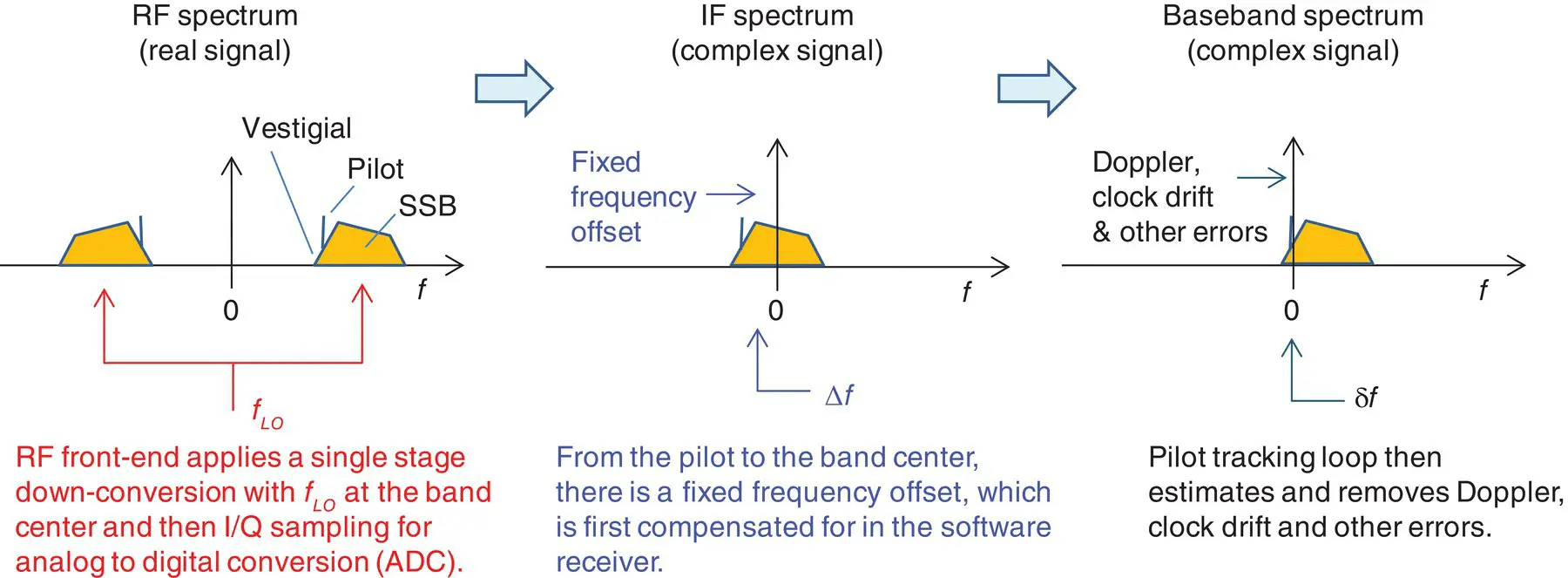
Figure 40.3 Recovery of single sideband signals.
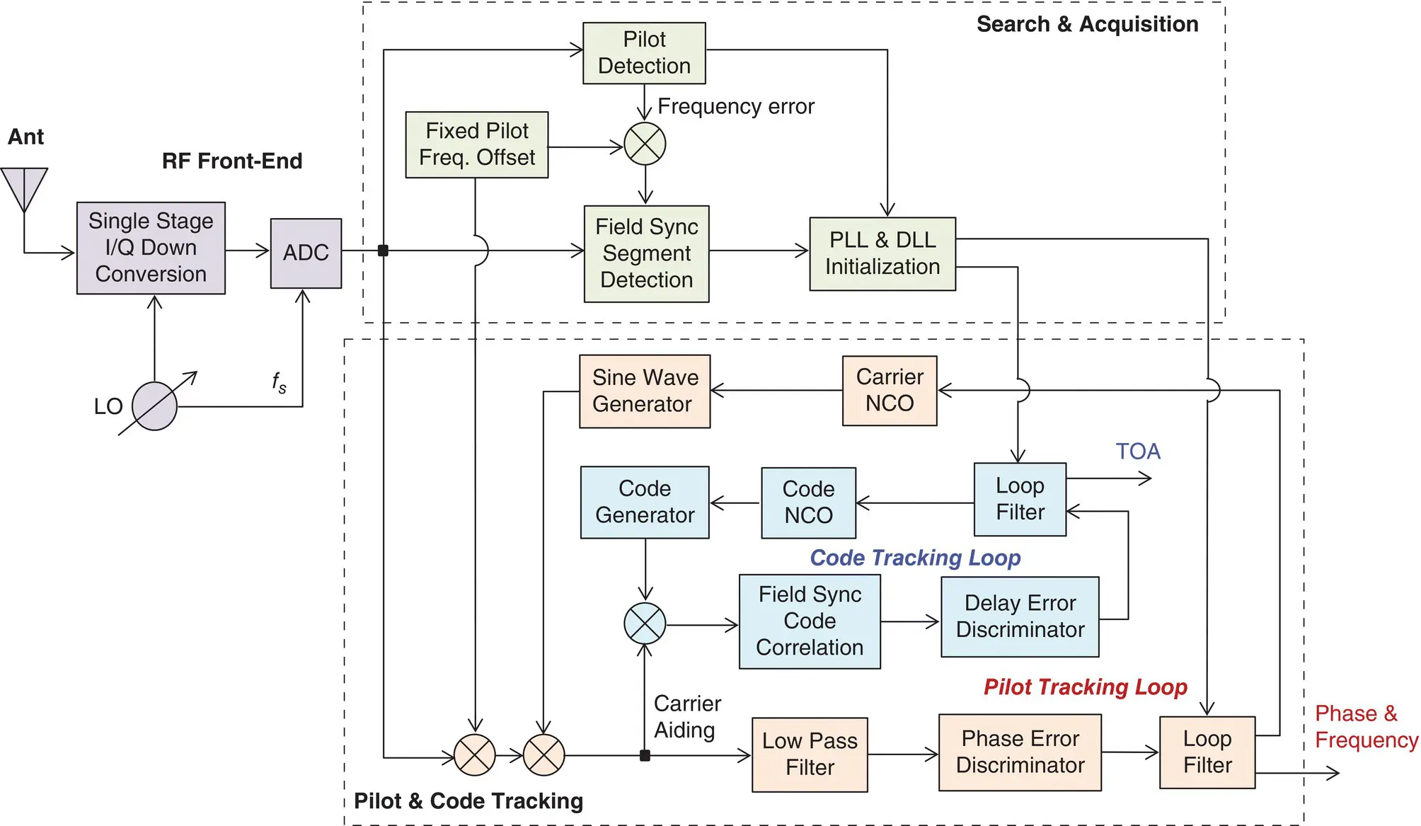
Figure 40.4 Architecture of an ATSC‐8VSB baseband signal processor with TOA tracking.
Figure 40.4is the block diagram of a DTV software receiver. It has two major systems. The top portion shows the acquisition search system, which includes two major steps, namely, pilot detection and field sync segment detection. The pilot detection step provides an estimate of the frequency error off the nominal pilot offset. The field sync segment detection determines an estimate of the code phase error and an estimate of the symbol rate error. These estimates are then used to initialize the code tracking delay lock loop (DLL) and pilot tracking phase lock loop (PLL).
The bottom portion of Figure 40.4shows the pilot and code tracking loops. After removing the nominal pilot frequency offset, the signal is low‐pass‐filtered to select the pilot signal while filtering out the wideband video signals. A phase error discriminator is applied to obtain an estimate of the phase error, which is processed by the loop filter. The estimated frequency error is used to adjust the carrier NCO, which in turn drives the carrier replica generator.
The code tracking loop acts as an inner loop as shown in Figure 40.4. The early, prompt, and late correlators provide an estimate of the timing error, which is processed by the loop filter to provide an estimate of the code delay and symbol rate. The latter is used to drive the code NCO, which in turn controls the code generator.
It is important to note that the pilot tracking loop is closed at the segment rate, whereas the code tracking loop is closed at the field rate. There are 313 segments per field. The duty cycle is 0.3%. In other words, the code loop has a rather low updating rate or a long updating period over which the code may shift several symbols. It is thus critical to obtain a good symbol error rate in order to maintain code lock. The carrier to code aiding is therefore applied.
The results of acquisition and tracking of real ATSC‐8VSB signals are now presented to illustrate the functionality and performance of the software receiver shown in Figure 40.4[11, 23, 29]. Figure 40.5(a) shows the signal spectrum (via the fast Fourier transform, or FFT), where the strong pilot signal is visible together with the 6 MHz signal sideband. Figure 40.5(b) shows the search results in terms of correlation versus search steps (per segment). When the code replica is the code for Field 1, the larger peak corresponds to Field 1 while the smaller peak corresponds to Field 2. Note that the separation between the two peaks is exactly 313 segments apart per signal spec.
Figure 40.6shows the code and pilot tracking results. Figure 40.6(a) shows the correlation function over 7 lags, each spaced by ½ symbols. Due to the low update rate (only once every 313 segments) and jitter in symbol rate, the conventional three‐correlator structure (i.e. the early, prompt, and late correlators) may no longer be capable of maintaining lock, particularly during large motion‐induced transients.
Figure 40.6(b) shows the correlation versus frequency offset from the nominal value. Since the receiver is stationary, this large offset is largely due to transmitter and/or receiver clock drift errors. Figure 40.6(c) shows the correlation peaks over a field of 313 segments. It is this operation that detects the field sync segment and identifies the peak location.
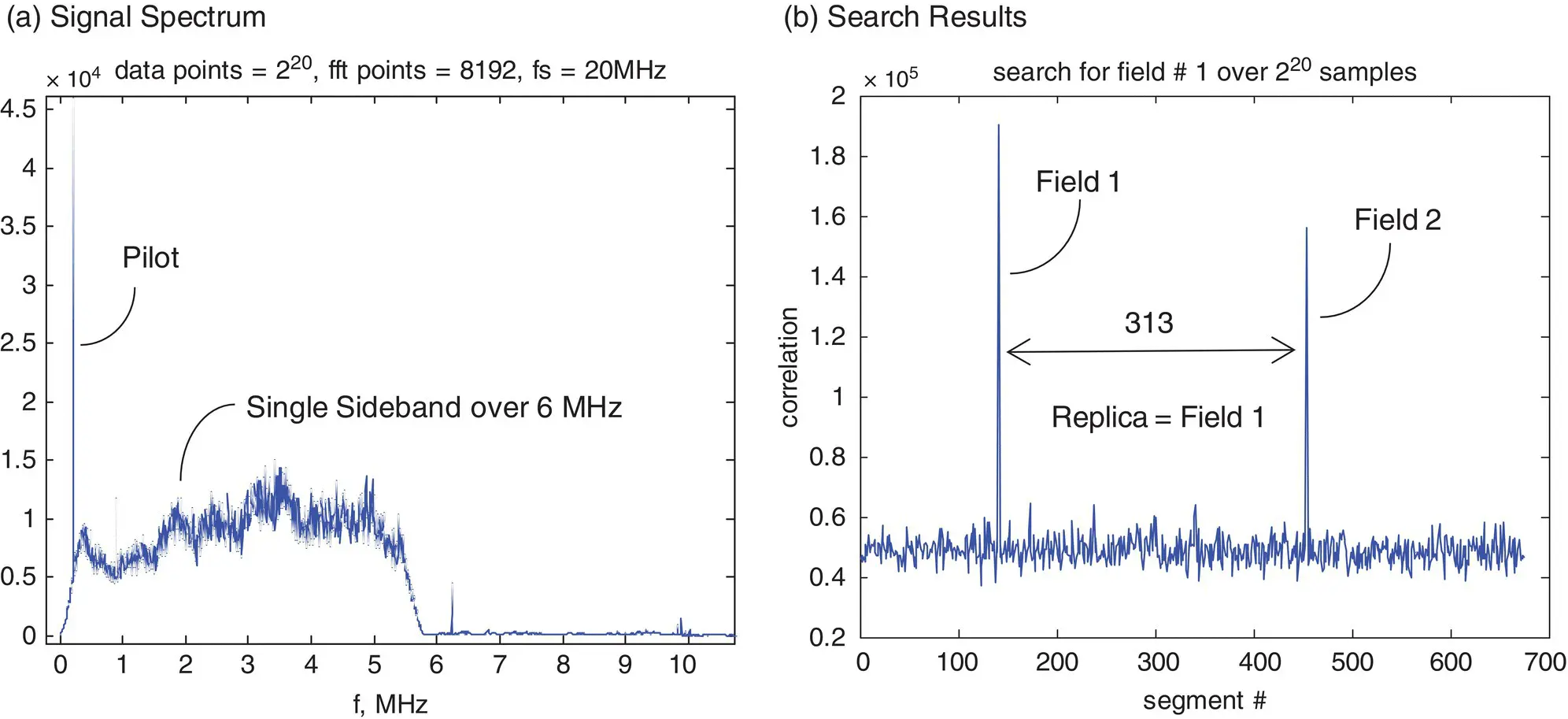
Figure 40.5 Acquisition of DTV signals.
Figure 40.6(d) shows the in‐phase (real) and quadrature (imaginary) components of the prompt channel (complex). The quadrature component goes to near zero, while the in‐phase component holds most of the signal power. Due to an initial sign, the in‐phase is negative in this plot. The quadrature is not zero but is biased, likely due to the fact that the code used as the replica for correlation is not balanced. Figures 40.6(e) and (f) show the code error (in symbols) and symbol rate error (in symbols per seconds) from the DLL loop.
Читать дальшеИнтервал:
Закладка:
Похожие книги на «Position, Navigation, and Timing Technologies in the 21st Century»
Представляем Вашему вниманию похожие книги на «Position, Navigation, and Timing Technologies in the 21st Century» списком для выбора. Мы отобрали схожую по названию и смыслу литературу в надежде предоставить читателям больше вариантов отыскать новые, интересные, ещё непрочитанные произведения.


Обсуждение, отзывы о книге «Position, Navigation, and Timing Technologies in the 21st Century» и просто собственные мнения читателей. Оставьте ваши комментарии, напишите, что Вы думаете о произведении, его смысле или главных героях. Укажите что конкретно понравилось, а что нет, и почему Вы так считаете.