Position, Navigation, and Timing Technologies in the 21st Century
Здесь есть возможность читать онлайн «Position, Navigation, and Timing Technologies in the 21st Century» — ознакомительный отрывок электронной книги совершенно бесплатно, а после прочтения отрывка купить полную версию. В некоторых случаях можно слушать аудио, скачать через торрент в формате fb2 и присутствует краткое содержание. Жанр: unrecognised, на английском языке. Описание произведения, (предисловие) а так же отзывы посетителей доступны на портале библиотеки ЛибКат.
- Название:Position, Navigation, and Timing Technologies in the 21st Century
- Автор:
- Жанр:
- Год:неизвестен
- ISBN:нет данных
- Рейтинг книги:5 / 5. Голосов: 1
-
Избранное:Добавить в избранное
- Отзывы:
-
Ваша оценка:
Position, Navigation, and Timing Technologies in the 21st Century: краткое содержание, описание и аннотация
Предлагаем к чтению аннотацию, описание, краткое содержание или предисловие (зависит от того, что написал сам автор книги «Position, Navigation, and Timing Technologies in the 21st Century»). Если вы не нашли необходимую информацию о книге — напишите в комментариях, мы постараемся отыскать её.
Volume 1 of
contains three parts and focuses on the satellite navigation systems, technologies, and engineering and scientific applications. It starts with a historical perspective of GPS development and other related PNT development. Current global and regional navigation satellite systems (GNSS and RNSS), their inter-operability, signal quality monitoring, satellite orbit and time synchronization, and ground- and satellite-based augmentation systems are examined. Recent progresses in satellite navigation receiver technologies and challenges for operations in multipath-rich urban environment, in handling spoofing and interference, and in ensuring PNT integrity are addressed. A section on satellite navigation for engineering and scientific applications finishes off the volume.
Volume 2 of
consists of three parts and addresses PNT using alternative signals and sensors and integrated PNT technologies for consumer and commercial applications. It looks at PNT using various radio signals-of-opportunity, atomic clock, optical, laser, magnetic field, celestial, MEMS and inertial sensors, as well as the concept of navigation from Low-Earth Orbiting (LEO) satellites. GNSS-INS integration, neuroscience of navigation, and animal navigation are also covered. The volume finishes off with a collection of work on contemporary PNT applications such as survey and mobile mapping, precision agriculture, wearable systems, automated driving, train control, commercial unmanned aircraft systems, aviation, and navigation in the unique Arctic environment.
In addition, this text:
Serves as a complete reference and handbook for professionals and students interested in the broad range of PNT subjects Includes chapters that focus on the latest developments in GNSS and other navigation sensors, techniques, and applications Illustrates interconnecting relationships between various types of technologies in order to assure more protected, tough, and accurate PNT
will appeal to all industry professionals, researchers, and academics involved with the science, engineering, and applications of position, navigation, and timing technologies.pnt21book.com
Position, Navigation, and Timing Technologies in the 21st Century — читать онлайн ознакомительный отрывок
Ниже представлен текст книги, разбитый по страницам. Система сохранения места последней прочитанной страницы, позволяет с удобством читать онлайн бесплатно книгу «Position, Navigation, and Timing Technologies in the 21st Century», без необходимости каждый раз заново искать на чём Вы остановились. Поставьте закладку, и сможете в любой момент перейти на страницу, на которой закончили чтение.
Интервал:
Закладка:
Figure 40.8shows the process of generating an OFDM symbol for DVB‐T signals. The payload data are mapped into QAM after source coding and channel coding. Each OFDM frame also contains transmission parameter signaling (TPS) symbols, which are coded and assigned to specific carriers. For our purpose, we are interested in scattered pilot cells and continual pilot carriers. These pilots are intended for time synchronization, frequency synchronization, channel estimation, frame synchronization, transmission mode identification, and phase noise estimation among others, whose transmitted power is “boosted” by a factor of 4/3 relative to data and TPS carriers. We will use them for timing, ranging, and ultimately positioning.
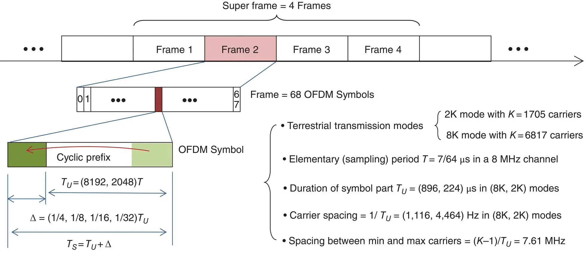
Figure 40.7 Frame structure of DVB‐T signals.
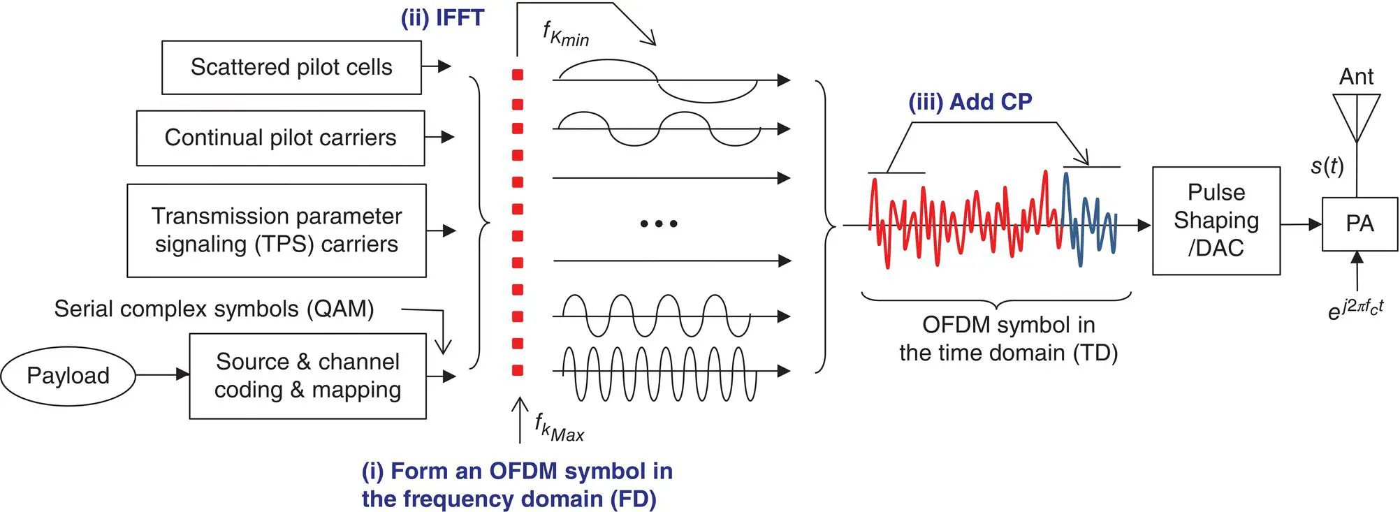
Figure 40.8 Generation of an OFDM symbol for DVB‐T signals.
For each OFDM symbol, the continual pilots remain at the same carrier indexes, namely, k = (0, 48, 54 … 1491, 1683, 1704, 1752, 1758, 1791 … 6603, 6795, and 6816) [44]. The 2K mode stops at K max= 1704 (a total of 45 carriers) while the 8K mode continues until reaching K max= 6816 (a total of 177 carriers), as illustrated in Figure 40.9.
The scattered pilots are placed at the carrier indexes that belong to the subset { k : k = K min+ 3×( l mod 4) + 12 p ≤ K maxfor l = 0, 1, …, 67 and p ≥ 0}, a total of 142 and 568 carriers per symbol for the 2K and 8K modes, respectively. The placement pattern repeats every four OFDM symbols. As shown in Figure 40.9, the pilots are inserted once every 12 carriers with the starting index being 12, 3, 6, and 9 for symbol 0, 1, 2, and 3, and so on. Note that the scattered pilots may coincide with the continual pilot carriers (11 and 44 carriers in common per symbol for the 2K and 8K modes, respectively). Each continual pilot coincides with a scattered pilot once every fourth symbol. There are 17 and 68 carriers for TPS in the 2K and 8K modes, respectively. As a result, there are 1512 useful data carriers in the 2K mode and 6048 in the 8K mode, respectively.
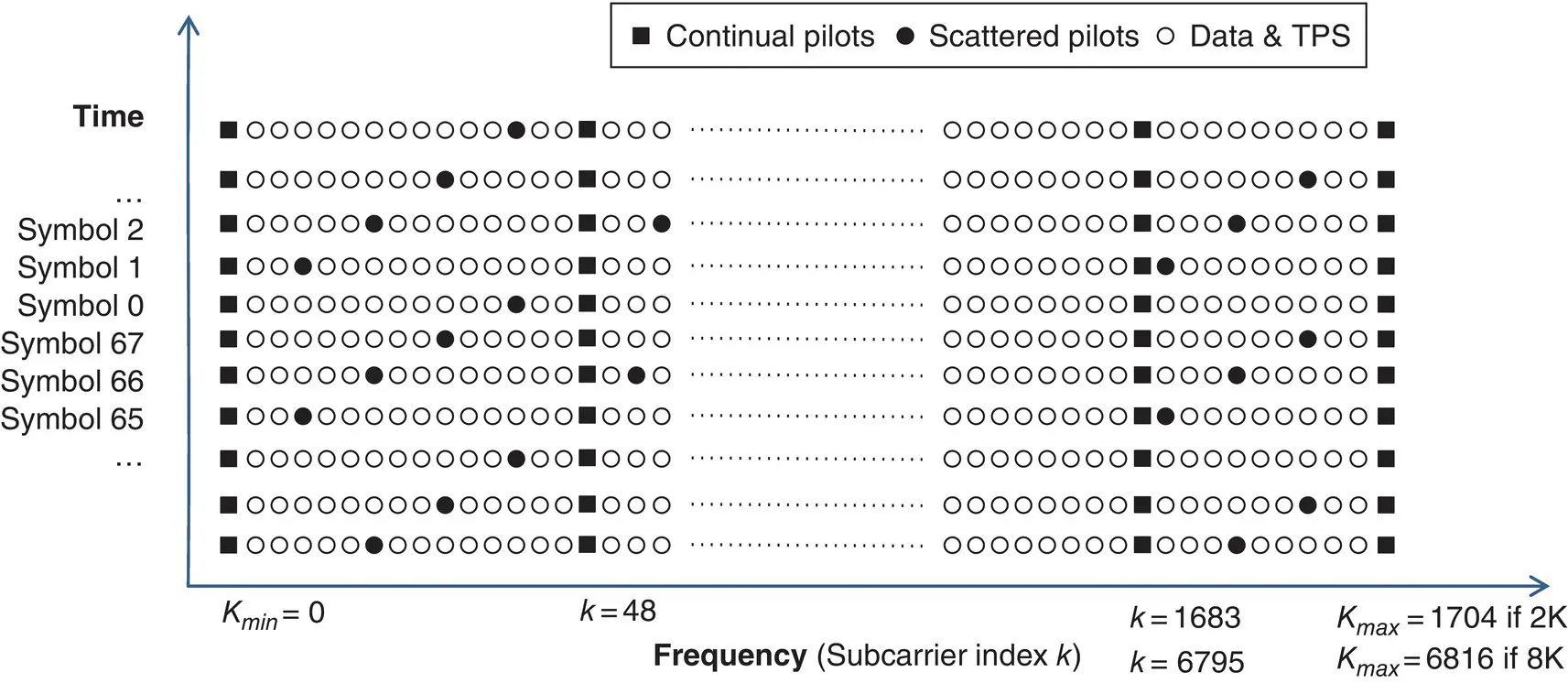
Figure 40.9 Pilot organization for DVB‐T signals (not to scale).
Furthermore, the continual and scattered pilots are modulated according to the pseudorandom binary sequence (PRBS) specified by the polynomial generator G PRBS( x ) = x 11+ x 9+ 1 with the all‐one initial condition. The PRBS is initialized such that the first output bit from the PRBS corresponds to the first active carrier, and a new value is generated by the PRBS on every used carrier of an OFDM symbol, whether it is a pilot or not.
Figure 40.10shows the architecture of a software OFDM receiver for TOA estimation with DVB‐T signals. The top part of Figure 40.10shows the typical processing steps employed by an OFDM communications receiver for the purpose of demodulating information data bits. The bottom part of Figure 40.10shows the extra processing steps of three possible methods to extract refined TOA measurements for the purpose of ranging and positioning.
After passing through a fading channel h ( τ ) with L discrete multipath components, the transmitted signal s ( t ) arrives at the receiver as r ( t ), which is captured by the antenna, and down‐converted from RF to a suitable IF for sampling or resampling if necessary. The sampling rate f sis typically a multiple of the fundamental rate (1/ T ). Once in the digital domain, the first operation is to determine the start sample of an OFDM symbol, which is called coarse symbol synchronization. A popular method for coarse symbol sync is to find a match between two blocks of samples that are a symbol apart (i.e., the cyclic prefix) by searching through the samples sequentially. A match is found when a first block of N CP= Δ/ T samples (over the cyclic prefix) correlates with a second block that is N FFTsamples later (over the symbol end). The peak location of the complex correlation points to the start of an OFDM symbol, used as an estimate of the integer STO, while the phase of the complex correlation provides a coarse estimate of the fractional CFO because the phase is only measured within ± π . The fractional CFO thus estimated is then removed from the samples by phase rotation (multiplying the samples by a complex exponential of the CFO estimate).
Since the coarse estimate of the symbol start via cyclic prefix matching may be off by ±50 samples, to ensure that the FFT window starts within a safe zone of cyclic prefix, the FFT window is purposely adjusted ahead of the peak location by a certain number of samples. This adjustment introduces an extra phase due to the circular shift property of cyclic prefix, which is readily absorbed into the channel model together with a fractional STO. They are ultimately removed in channel equalization, and thus data demodulation is not affected. Note that the start sample of each sliding FFT window, plus the number of advanced samples, and the fractional STO together constitute the TOA estimate (the start of an OFDM symbol) in the receiver’s local time. However, the TOA estimates are coarse and are typically not tracked over time in a wireless communications receiver. It is one of the reasons a refined TOA estimation and tracking process is needed for PNT.
FFT is applied to the samples within the sliding window, yielding a frequency‐domain representation of an OFDM symbol. After the fractional CFO correction, the spectrum (the received frequency‐domain signal) may still be subject to a shift by a number of frequency bins (subcarriers) equal to an integer CFO if present. Since the continual pilots are shifted by the same amount, the integer CFO can be estimated by determining where the continual pilots reside in the spectrum. Correlation between the continual pilot subcarriers of two consecutive symbols reaches the maximum value when the nominal continual pilot indexes are adjusted up or down by an amount equal to the integer CFO. Furthermore, the phase of the correlation peak between the continual pilots of two consecutive symbols can be used to estimate the residual fractional CFO and the SCO. The integer CFO is then easily corrected by spectrum shift (re‐indexing).
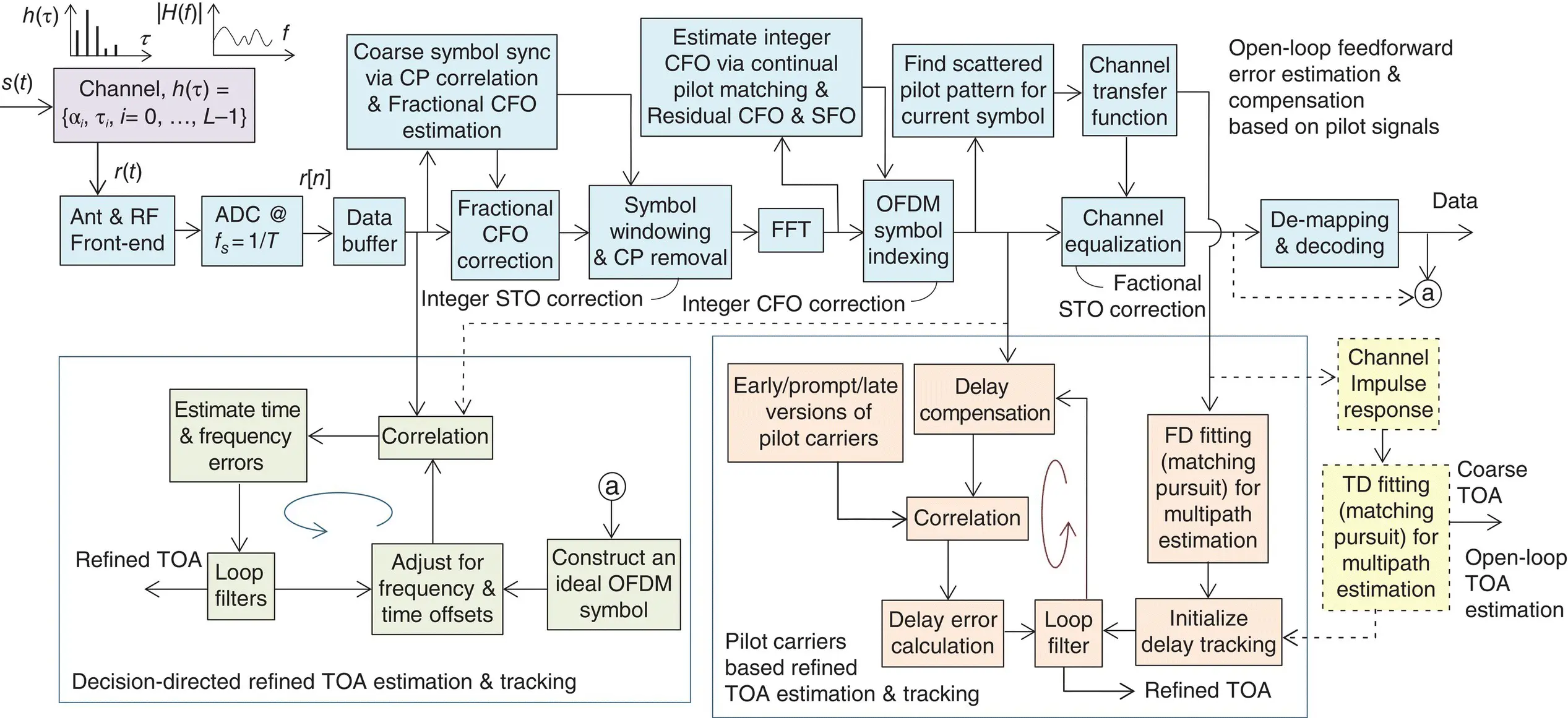
Figure 40.10 Architecture of a DVB‐T OFDM signal processor with TOA tracking.
There are four insertion patterns of scattered pilots in successive symbols, and each pattern therefore repeats once every four symbols. The particular insertion pattern of a received symbol can be determined by correlating its scattered pilot subcarriers with those at the indexes of four possible patterns. Four correlations are therefore calculated, one for each possible insertion pattern, and the one that produces the maximum correlation value is the pattern present in the current symbol.
Once the pattern of scattered pilots is found for the current symbol, the scattered pilots together with continual pilots extracted from the current symbol (as received) are scaled by those from a local replica (as transmitted) to afford an estimate of the channel frequency response (transfer function) at the pilot subcarrier frequencies. As shown in Figure 40.9, the spacing is 12 subcarriers between scattered pilots. As a result, a linear frequency interpolation can be applied to extend the estimated frequency response from the pilot subcarriers to the full used OFDM subcarriers.
Читать дальшеИнтервал:
Закладка:
Похожие книги на «Position, Navigation, and Timing Technologies in the 21st Century»
Представляем Вашему вниманию похожие книги на «Position, Navigation, and Timing Technologies in the 21st Century» списком для выбора. Мы отобрали схожую по названию и смыслу литературу в надежде предоставить читателям больше вариантов отыскать новые, интересные, ещё непрочитанные произведения.


Обсуждение, отзывы о книге «Position, Navigation, and Timing Technologies in the 21st Century» и просто собственные мнения читателей. Оставьте ваши комментарии, напишите, что Вы думаете о произведении, его смысле или главных героях. Укажите что конкретно понравилось, а что нет, и почему Вы так считаете.