Yong Bai - Deepwater Flexible Risers and Pipelines
Здесь есть возможность читать онлайн «Yong Bai - Deepwater Flexible Risers and Pipelines» — ознакомительный отрывок электронной книги совершенно бесплатно, а после прочтения отрывка купить полную версию. В некоторых случаях можно слушать аудио, скачать через торрент в формате fb2 и присутствует краткое содержание. Жанр: unrecognised, на английском языке. Описание произведения, (предисловие) а так же отзывы посетителей доступны на портале библиотеки ЛибКат.
- Название:Deepwater Flexible Risers and Pipelines
- Автор:
- Жанр:
- Год:неизвестен
- ISBN:нет данных
- Рейтинг книги:4 / 5. Голосов: 1
-
Избранное:Добавить в избранное
- Отзывы:
-
Ваша оценка:
Deepwater Flexible Risers and Pipelines: краткое содержание, описание и аннотация
Предлагаем к чтению аннотацию, описание, краткое содержание или предисловие (зависит от того, что написал сам автор книги «Deepwater Flexible Risers and Pipelines»). Если вы не нашли необходимую информацию о книге — напишите в комментариях, мы постараемся отыскать её.
,, has been created to meet the needs of engineers and scientists to keep them up to date and informed of all of these advances. This second volume in the series focuses on flexible pipelines, risers, and umbilicals, offering the engineer the most thorough coverage of the state-of-the-art available. The authors of this work have written numerous books and papers on these subjects and are some of the most influential authors on flexible pipes in the world, contributing much of the literature on this subject to the industry. This new volume is a presentation of some of the most cutting-edge technological advances in technical publishing.
The first volume in this series, published by Wiley-Scrivener, is
, available at www.wiley.com. Laying the foundation for the series, it is a groundbreaking work, written by some of the world’s foremost authorities on pipes and pipelines. Continuing in this series, the editors have compiled the second volume, equally as groundbreaking, expanding the scope to pipelines, risers, and umbilicals.
This is the most comprehensive and in-depth series on pipelines, covering not just the various materials and their aspects that make them different, but every process that goes into their installation, operation, and design. This is the future of pipelines, and it is an important breakthrough. A must-have for the veteran engineer and student alike, this volume is an important new advancement in the energy industry, a strong link in the chain of the world’s energy production
Deepwater Flexible Risers and Pipelines — читать онлайн ознакомительный отрывок
Ниже представлен текст книги, разбитый по страницам. Система сохранения места последней прочитанной страницы, позволяет с удобством читать онлайн бесплатно книгу «Deepwater Flexible Risers and Pipelines», без необходимости каждый раз заново искать на чём Вы остановились. Поставьте закладку, и сможете в любой момент перейти на страницу, на которой закончили чтение.
Интервал:
Закладка:
5 (5) As in future work, a validation against test data is recommended for both the ABAQUS and Analytical models.
References
1. Fernando, U. S., Sheldrake, T., Tan, Z., and Clements, R., 2004, “The Stress Analysis and Residual Stress Evaluation of Pressure Armor Layers in Flexible Pipes Using 3D Finite Element Models,” Proceedings of ASME 23 rdInternational Conference on Offshore Mechanics and Arctic Engineering.
2. Neto, A. G., de Arruda Martins, C., Pesce, C. P., Meirelles, C. O. C., Malta, E. R., Neto, T. F. B., and Godinho, C. A. F., 2013, “Prediction of Burst in Flexible Pipes”, Journal of Offshore Mechanics and Arctic Engineering, 135, 1, 011401.
3. De Oliveira, J. G., Goto, Y., and Okamoto, T., 1985, “Theoretical and methodological approaches to flexible pipe design and application”, In Proceedings. Offshore Technology Conference. New York NY[PROC. OFFSHORE TECHNOL. CONF.]. Vol. 3, pp. 517.
4. Zhu X K, Leis B N. Average shear stress yield criterion and its application to plastic collapse analysis of pipelines[J]. International Journal of Pressure Vessels and Piping, 2006, 83(9): 663–671.
5. Chen B, Nielsen R, Colquhoun R S. Theoretical models for prediction of burst and collapse and their verification by testing[C]. Flexible Pipe Technology-International Seminar on Recent Research and Development, Norway. 1992.
6. D. Fergestad and S. A. Løtveit, Handbook on design and operation of flexible pipes[R]. 2014.
7. Kebadze E. Theoretical modelling of unbonded flexible pipe cross-sections[D]. South Bank University, 2000.
8. Knapp R H. Derivation of a new stiffness matrix for helically armoured cables considering tension and torsion[J]. International Journal for Numerical Methods in Engineering, 1979, 14(4): 515–529.
9. API 17J. Specification for unbonded flexible pipe[S]. Washington, DC: American Petroleum Institute, 2014.
10. Witz, J. A. (1996). A case study in the cross-section analysis of flexible risers. Marine Structures, 9(9), 885–904.
11. Bai Y, Chen W, Xiong H, et al . Analysis of steel strip reinforced thermoplastic pipe under internal pressure. Ships Offshore Struct 2015:1–8.
4
Tensile Behavior of Flexible Pipes
4.1 Introduction
Flexible pipelines must be designed considering the extreme situation for which additional components are needed against severe loading and environmental conditions. Tensile armor is employed in case of high tensile forces, which increase with water depth; and massive components used against high internal and external pressures. In this chapter, the mechanical behavior of the pipe under pure tension is investigated by both theoretical and numerical analysis, and then, the contribution of the external pressure to the axial problem is examined using an analytical analysis. As the deformations along the longitudinal direction of the studied pipe highly depend on the radial stiffness of the cross section, the influence of the pressure armor is carefully evaluated in the inception phase, and its radial stiffness is verified by its own numerical results. The plastic behavior for both steel and polymer layers is taken into account by using the secant modulus method. Moreover, this work answers a question raised by producers that need to know when tensile armor is required to reinforce Metallic Strip Flexible Pipes (MSFP). The theoretical model is employed to carry out the comparison between pipes with different configurations, in order to investigate the influencing parameters of the tensile stiffness. The results obtained from the theoretical and the numerical simulations lead to a remarkable confidence in the analytical solution thanks to a relatively small difference between the outcomes. This chapter is quoted from Ref. [1]. A more detailed configuration of the strip-wound flexible tubing can be found in the relevant literature [2, 3]. Knapp et al . [4, 5] used the energy method to study the stiffness matrix of the spiral reinforcement layer under tensile and torsional loads, and derived some classic formulas. Feret et al . [6] proposed a simplified formula to calculate different stresses and contact pressures under axisymmetric loads. Ramos et al . [7, 8] made some additional contributions to the pipeline response. Saevik[9–11] has developed a model to predict the stress of axisymmetric effects Dong [12], Guo [13], and Neto [20] made further research on the mechanical model of flexible pipe from the perspective of virtual work principle.
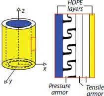
Figure 4.1 Linear-longitudinal profile.
4.2 Theoretical Models
4.2.1 Mechanical Model of Pressure Armor Layer
The benchmark analyzed in this chapter focuses on a composite pipe composed of one pressure armor layer and two conversely winded tensile armor layers embedded into two HDPE layers, as in Figure 4.1.
The theoretical model is based on two main hypotheses.
The contribution of the pressure armor due to the axial strength can be neglected in terms of tensile resistance as the winding angle is close to 90°, as discussed by De Sousa [14]. While, it confers most of the radial stiffness, which highly influences the tensile capacity of the pipe.
The contribution of the HDPE layers to the radial stiffness is neglected. This is possible due to the presence of the pressure armor layer, which gives the main contribution in terms of radial stiffness.
Therefore, the computation in radial direction is reduced into two components: pressure armor layer and tensile armor layers. No initial gaps between different layers are assumed. Winding angle and thickness variations, as well as friction are neglected [15].
The tensile response of the pipe is estimated considering tensile force and external pressure at the same time. The external pressure Pext can be applied directly on the external surface of the outermost tensile armor layer due to the weakness of the surrounding HDPE coat. The tensile contribution of HDPE cylinders is included in calculating the total tensile resistance.
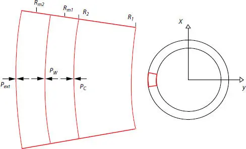
Figure 4.2 Contact pressures between layers mechanical model of pressure armor layer.
According to what has been already discussed in the paper by Yue et al . [15], the authors in the present contribution are considering the same assumptions for the present study. Such simplification does not affect the results which are in very good agreement with the numerical model. Pressures can lead to radial contraction of the layers, which can reduce the tension stiffness of the flexible pipe. It is possible to study tensile and pressure armors separately, in order to get the radial displacements of each layer. Let PC be the contact pressure between the pressure armor and the innermost tensile armor layer, while PW represents the contact pressure between the tensile armor layers, as shown in Figure 4.2, where R m1and R m2are the mean radii of the tensile armor, R 1and R 2are inner and outer radii of the pressure armor, respectively.
When subjected to tensile loading, the resistance of the flexible pipe is influenced by its radial stiffness due to the helical structure of the layers. The first effort of this chapter is to investigate the radial stiffness of the pressure armor in order to obtain relatively accurate results for this axial problem. Due to its complex shape, which shows different properties in longitudinal and transverse directions, an equivalent theoretical model is used to simplify the computation. The use of negligible elastic modulus in the longitudinal direction is a common practice in the study of equivalent helical structures of flexible pipelines with winding angle close to 90° using analytical approaches. Such null modulus is not considered in the FE analysis (which has actual mechanical properties of the materials used). In fact, the pressure armor layer can be seen as an orthotropic cylinder, with Young’s modulus equal to zero along the longitudinal direction, while in the radial direction its equivalent thickness heq and Young’s modulus Eeq are computed as previously done by De Sousa [14]:
Читать дальшеИнтервал:
Закладка:
Похожие книги на «Deepwater Flexible Risers and Pipelines»
Представляем Вашему вниманию похожие книги на «Deepwater Flexible Risers and Pipelines» списком для выбора. Мы отобрали схожую по названию и смыслу литературу в надежде предоставить читателям больше вариантов отыскать новые, интересные, ещё непрочитанные произведения.


Обсуждение, отзывы о книге «Deepwater Flexible Risers and Pipelines» и просто собственные мнения читателей. Оставьте ваши комментарии, напишите, что Вы думаете о произведении, его смысле или главных героях. Укажите что конкретно понравилось, а что нет, и почему Вы так считаете.