Yong Bai - Deepwater Flexible Risers and Pipelines
Здесь есть возможность читать онлайн «Yong Bai - Deepwater Flexible Risers and Pipelines» — ознакомительный отрывок электронной книги совершенно бесплатно, а после прочтения отрывка купить полную версию. В некоторых случаях можно слушать аудио, скачать через торрент в формате fb2 и присутствует краткое содержание. Жанр: unrecognised, на английском языке. Описание произведения, (предисловие) а так же отзывы посетителей доступны на портале библиотеки ЛибКат.
- Название:Deepwater Flexible Risers and Pipelines
- Автор:
- Жанр:
- Год:неизвестен
- ISBN:нет данных
- Рейтинг книги:4 / 5. Голосов: 1
-
Избранное:Добавить в избранное
- Отзывы:
-
Ваша оценка:
Deepwater Flexible Risers and Pipelines: краткое содержание, описание и аннотация
Предлагаем к чтению аннотацию, описание, краткое содержание или предисловие (зависит от того, что написал сам автор книги «Deepwater Flexible Risers and Pipelines»). Если вы не нашли необходимую информацию о книге — напишите в комментариях, мы постараемся отыскать её.
,, has been created to meet the needs of engineers and scientists to keep them up to date and informed of all of these advances. This second volume in the series focuses on flexible pipelines, risers, and umbilicals, offering the engineer the most thorough coverage of the state-of-the-art available. The authors of this work have written numerous books and papers on these subjects and are some of the most influential authors on flexible pipes in the world, contributing much of the literature on this subject to the industry. This new volume is a presentation of some of the most cutting-edge technological advances in technical publishing.
The first volume in this series, published by Wiley-Scrivener, is
, available at www.wiley.com. Laying the foundation for the series, it is a groundbreaking work, written by some of the world’s foremost authorities on pipes and pipelines. Continuing in this series, the editors have compiled the second volume, equally as groundbreaking, expanding the scope to pipelines, risers, and umbilicals.
This is the most comprehensive and in-depth series on pipelines, covering not just the various materials and their aspects that make them different, but every process that goes into their installation, operation, and design. This is the future of pipelines, and it is an important breakthrough. A must-have for the veteran engineer and student alike, this volume is an important new advancement in the energy industry, a strong link in the chain of the world’s energy production
Deepwater Flexible Risers and Pipelines — читать онлайн ознакомительный отрывок
Ниже представлен текст книги, разбитый по страницам. Система сохранения места последней прочитанной страницы, позволяет с удобством читать онлайн бесплатно книгу «Deepwater Flexible Risers and Pipelines», без необходимости каждый раз заново искать на чём Вы остановились. Поставьте закладку, и сможете в любой момент перейти на страницу, на которой закончили чтение.
Интервал:
Закладка:
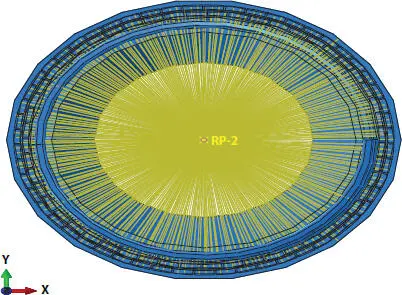
Figure 3.5 Kinematic Coupling at RP-2.
In order to accurately obtain the thickness change of each layer and the stress change along the thickness direction, solid elements are used to simulate each layer of the model. C3D8I element is used in cylindrical layers; this kind of element is a non- conforming mode element. It can overcome the self-locking of shear force in the first- order element with complete integration. It can obtain high precision results by using fewer elements, but it is sensitive to the distortion of the element. Therefore, all the spiral armor layers use C3D8R cell. More refined mesh partition can avoid hourglass problems that may exist in this kind of cell. The detailed meshing of the model is shown in Figure 3.6.
The model used in this chapter is compared with the experimental data of public tables to verify the feasibility of the FEA model. The test was recorded in a paper published by J. A. Witz [10]. The most common way to evaluate whether the simulation produces the correct result is to study the energy in the model. ALLKE is the kinetic energy of whole model, while ALLIE is a summation of all internal energy quantities. As a general rule, the kinetic energy of the deforming material should not exceed a small fraction (typically 10%) of its internal energy throughout most of the process. As shown in Figure 3.7, it can be seen that during the simulation process, the ratio of kinetic energy to internal energy is less than 10% in the general. This shows the correctness of the simulation. In addition, artificial strain energy associated with constraints used to remove singular modes (such as hourglass control), and with constraints used to make the drill rotation follow the in-plane rotation of the shell elements. The artificial strain energy is below approximately 10% of the total internal energy, indicating that hourglass is not a problem. In order to reduce the influence of the hourglass energy, the ratio of artificial strain energy to strain energy is extracted as shown in Figure 3.8. With the loading process, it can be seen that the ratio is smaller than 5%, which indicates the hourglass energy is quite small and the result of the simulation is reliable. But, when the pressure occurs to 80 MPa approximately, the curve rises sharply which indicates that the pressure might reach to the ultimate strength and the model appears the large deformation. From the result of Figures 3.7and 3.8, it can be regarded that the FEA model is correct.
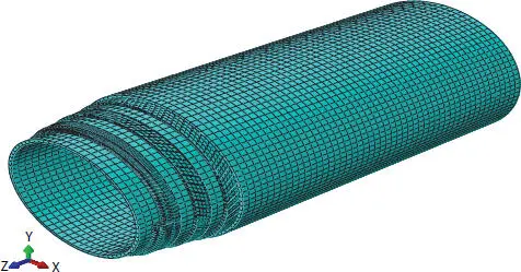
Figure 3.6 Meshing of the flexible pipe model.
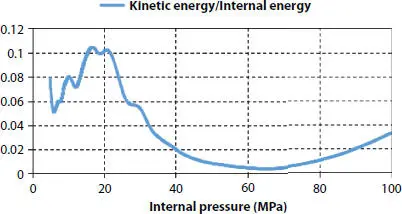
Figure 3.7 Kinetic energy/internal energy curve.
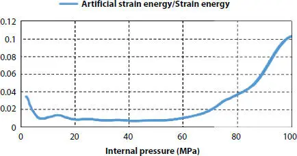
Figure 3.8 Artificial strain energy/strain energy curve.
3.4 Result and Discussion
It should be noted that this chapter is limited to prediction of pressure armor stresses during pipe operation only, and that the residual wires stresses from manufacturing are disregarded and not taken in consideration. Analytical models follow a series of restrictive assumptions while finite element models are not limited to them. Thus, there will be a certain error between these two analysis methods. Theoretical models and finite element models are carried out respectively to exam the behavior of a flexible pipe under internal pressure. The numerical results are selected from the middle span of the flexible pipes since the stress near the reference points is inapplicable due to boundary conditions.
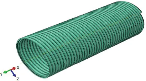
Figure 3.9 Model of pressure armor layer.
Pressure armor layer which shown in Figure 3.9is the main force-resistant structure of pipe under internal pressure. Figure 3.10shows the change of Mises stress of pressure armor in this section with the increase of internal pressure. In order to express the stress changes of its Z-section clearly, the range is fixed at 600 MPa, and red markers are used when it is higher than this value. It can be seen from the figure that the stress of Z-section decreases gradually from bottom to top, which accords with the general law of stress variation along the thickness direction of the section under internal pressure. Because of the shape of Z-section, the maximum stress points often occur at the left ends. With the increase of internal pressure, the inner part of the section yields first and then expands gradually to the outside. When the internal pressure is between 70 and 80 MPa, the whole section yields, the result is similar to the conclusion of the energy analysis.
Figure 3.11shows the relationship between maximum von Mises stress of pressure armor and the internal pressure. As can be seen, before the yielding of the pressure armor, the results of the two methods are in good agreement. After the yielding occurs, the errors of the two methods begin to appear. The growth rate of the Mises stress obtained from FEM is slower than that from the theory. The main reason is that the self-locking of the pressure armor in the finite element method will cause the redistribution of stress in the section, which makes it difficult to predict the stress. While the theoretical method doesn’t take this change into consideration. After yielding, the maximum von Mises stress of two models keep increasing slowly and the Matlab’s reaches to the ultimate strength firstly. Generally speaking, the difference between the two methods is not very big. The analytical result is 71 MPa while numerical result is 74 MPa when the maximum von Mises stress reaches to the yield strength. As for getting to the ultimate strength, the analytical result is 75 MPa while the numerical result is 80 MPa.
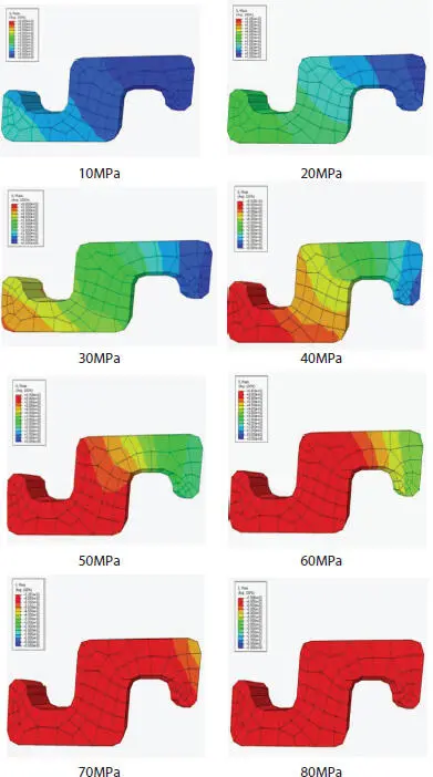
Figure 3.10 Mises stress of Z-shaped section.
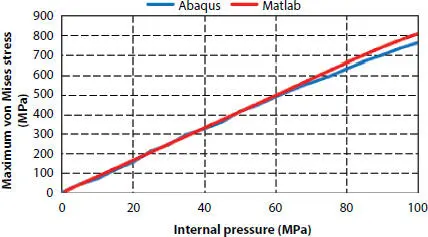
Figure 3.11 Pressure-maximum von Mises stress curve.
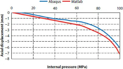
Figure 3.12 Pressure-axial displacement curve.
If the deformation of pipe is not restricted, the pipe cannot function normally. Figures 3.12and 3.13show the relationship between the axial displacement and the internal pressure and between the radial displacement and the internal pressure, respectively. The axial displacement takes the value of the coupling point RP2, and the radial displacement takes the value of the middle node of the Z-section selected. It can be found that the theoretical curve is in same trend with the finite element curve. While, FEM always lags behind the theoretical curve. This is because the deformation of the pressure armor will be limited by its self-locking structure, but this effect is not considered in the theoretical model. Therefore, in the subsequent deformation development, the finite element method needs more internal pressure to obtain the same deformation as the theoretical model. When the internal pressure continues to increase and reaches to the ultimate strength, the axial displacement and radial displacement begin to increase sharply. This also indicates that the pressure armor is the main internal pressure resistant structure. When it fails, it is considered that the pipe will soon fail.
Читать дальшеИнтервал:
Закладка:
Похожие книги на «Deepwater Flexible Risers and Pipelines»
Представляем Вашему вниманию похожие книги на «Deepwater Flexible Risers and Pipelines» списком для выбора. Мы отобрали схожую по названию и смыслу литературу в надежде предоставить читателям больше вариантов отыскать новые, интересные, ещё непрочитанные произведения.


Обсуждение, отзывы о книге «Deepwater Flexible Risers and Pipelines» и просто собственные мнения читателей. Оставьте ваши комментарии, напишите, что Вы думаете о произведении, его смысле или главных героях. Укажите что конкретно понравилось, а что нет, и почему Вы так считаете.