Yong Bai - Deepwater Flexible Risers and Pipelines
Здесь есть возможность читать онлайн «Yong Bai - Deepwater Flexible Risers and Pipelines» — ознакомительный отрывок электронной книги совершенно бесплатно, а после прочтения отрывка купить полную версию. В некоторых случаях можно слушать аудио, скачать через торрент в формате fb2 и присутствует краткое содержание. Жанр: unrecognised, на английском языке. Описание произведения, (предисловие) а так же отзывы посетителей доступны на портале библиотеки ЛибКат.
- Название:Deepwater Flexible Risers and Pipelines
- Автор:
- Жанр:
- Год:неизвестен
- ISBN:нет данных
- Рейтинг книги:4 / 5. Голосов: 1
-
Избранное:Добавить в избранное
- Отзывы:
-
Ваша оценка:
Deepwater Flexible Risers and Pipelines: краткое содержание, описание и аннотация
Предлагаем к чтению аннотацию, описание, краткое содержание или предисловие (зависит от того, что написал сам автор книги «Deepwater Flexible Risers and Pipelines»). Если вы не нашли необходимую информацию о книге — напишите в комментариях, мы постараемся отыскать её.
,, has been created to meet the needs of engineers and scientists to keep them up to date and informed of all of these advances. This second volume in the series focuses on flexible pipelines, risers, and umbilicals, offering the engineer the most thorough coverage of the state-of-the-art available. The authors of this work have written numerous books and papers on these subjects and are some of the most influential authors on flexible pipes in the world, contributing much of the literature on this subject to the industry. This new volume is a presentation of some of the most cutting-edge technological advances in technical publishing.
The first volume in this series, published by Wiley-Scrivener, is
, available at www.wiley.com. Laying the foundation for the series, it is a groundbreaking work, written by some of the world’s foremost authorities on pipes and pipelines. Continuing in this series, the editors have compiled the second volume, equally as groundbreaking, expanding the scope to pipelines, risers, and umbilicals.
This is the most comprehensive and in-depth series on pipelines, covering not just the various materials and their aspects that make them different, but every process that goes into their installation, operation, and design. This is the future of pipelines, and it is an important breakthrough. A must-have for the veteran engineer and student alike, this volume is an important new advancement in the energy industry, a strong link in the chain of the world’s energy production
Deepwater Flexible Risers and Pipelines — читать онлайн ознакомительный отрывок
Ниже представлен текст книги, разбитый по страницам. Система сохранения места последней прочитанной страницы, позволяет с удобством читать онлайн бесплатно книгу «Deepwater Flexible Risers and Pipelines», без необходимости каждый раз заново искать на чём Вы остановились. Поставьте закладку, и сможете в любой момент перейти на страницу, на которой закончили чтение.
Интервал:
Закладка:
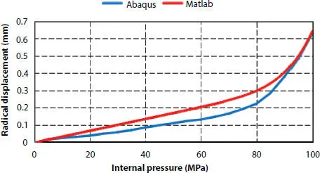
Figure 3.13 Pressure-radial displacement curve.
3.5 Design
It can be found that the results in two models are in good agreement and the theoretical model has high accuracy in predicting the burst pressure of pipe. The results may be of interest to the manufacture factory engineers. It is convenient to design the structure of pipes by using the theoretical model under different internal pressure and different given radius. Other most simplify formulas are proposed in Handbook [6] which are shown in the below. The contribution of tensile armor to burst pressure resistance is expressed by
(3.15) 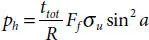
where ttot is the total thickness of the double tensile armor layers, R is the mean radius of layer, a is the winding angle, and σu is the ultimate tensile strength of the layer. The contribution of the tensile armor to end cap pressure resistance is expressed by
(3.16) 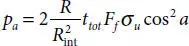
where R intis the inner radius of the layer. The contribution of the pressure armor to burst pressure resistance is expressed by
(3.17) 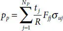
where tj denotes the thickness of pressure spiral with layer number j and R is the mean radius of the Np pressure layers, respectively. The fill factor Ffj for pressure spiral wire layer j . The total hoop pressure resistance is the obtained by summing the contribution from each layer as
(3.18) 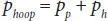
The burst pressure is then given by the smallest of phoop and pa :
(3.19) 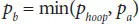
It can be seen that R , ttot , and a take most significant roles in influencing the burst pressure. In the design procedure, we can adjust these parameters to meet the design requirement. In shallow water, steel strip reinforced thermoplastic pipe (related materials are shown in Table 3.3) is often used. Bai [11] has done some researches on the mechanical responses of SSRTP under pressure loads. In order to design structure of pipes economically and safely, this chapter uses two theoretical models to predict burst pressure in more models (shown in Table 3.4) to illustrate the procedure of designing under different serve conditions.
Table 3.3 Steel strip geometrical properties.
| Models | 207 GPa |
| Ultimate stress | 960 MPa |
| Poisson radio | 0.3 |
| Profile | 0.5 mm × 52 mm |
| Winding angle | 54.7° |
Table 3.4 Models with different inner radius.
| Model | Inner radius | Layers |
|---|---|---|
| A1 | 25 mm | Internal sheath + four layers steel strips + out sheath |
| A2 | 25 mm | Internal sheath + six layers steel strips + out sheath |
| B1 | 50 mm | Internal sheath + pressure armor + two tensile armors = out sheath |
| B2 | 100 mm | Internal sheath + pressure armor + two tensile armors = out sheath |
Table 3.5 Prediction by two theoretical models.
| Mode1 | Theoretical mode 1 | Theoretical mode 2 |
|---|---|---|
| A1 | 43 MPa | 38 MPa |
| A2 | 55 MPa | 53 MPa |
| B1 | 134 MPa | 99 MPa |
| B2 | 38 MPa | 30 MPa |
In Table 3.5, it shows the prediction of theoretical model 2. It is always smaller than theoretical model 1’s, the main reason is that the theoretical model 2 doesn’t take the contribution of the cylindrical layers into consideration, so it is underestimated in Tables 3.4and 3.5, the procedure of design can be concluded as below.
By given small radius and pressure, take 25 mm and 30 MPa, for example, the four layers SSRTP could meet this requirement enough. While the internal pressure increases to about 50 MPa, it’s necessary to adjust the winding angle or add more layers to satisfy the requirement. When the given radius is more than 50 mm or pressure is more than 60 MPa, the SSRTP might not satisfy in this condition. In addition, the pressure armor and tensile armor are often used in big radius pipe to subjected to high pressure. If the requirement of radius or pressure keeps increasing, adjust the winding angle or thickness of pressure armor and tensile armor. Based on these conclusions, it is easily to design a software to design structure of pipes when the internal pressure increases. The flowchart is shown in Figure 3.14.
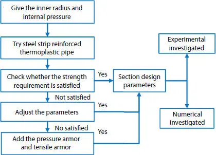
Figure 3.14 Computer design flowchart of pipe section.
3.6 Conclusions
Within this chapter, the burst behavior of the flexible pipe was investigated by both theoretical model and numerical simulation. The accuracy and reliability of the theoretical model is verified by the good agreement between the two sets of results. But it is worth noting that this chapter is limited to prediction of pressure armor stresses during pipe operation only, and that the residual wires stresses from manufacturing are disregarded and not taken in consideration. Also, a simplified software to design structure section with the given radius and internal pressure is presented, which can provide some references for the factory engineers. From the research, we can learn that:
1 (1) The results of the theoretical model show good linearity of flexible pipes under internal pressure in the elastic phase. Theoretical model adopted here is basically valid in calculating the physical quantities stated above according to the comparison with the FEM. But the theoretical model doesn’t take the self-locking of pressure armor into condition, so there are certain errors in the comparison.
2 (2) The result of theoretical model and numerical model shows when the pressure armor yields, the axial displacement and radial displacement begin to increase sharply, which indicates that the pressure armor is the main internal pressure resistant structure. For safety, it is acceptable to consider when pressure armor fails, the pipeline will soon fail.
3 (3) In the process of internal pressure loading, the stress of Z-shaped section increases gradually from inside to outside, and the inner part near the end yield first.
4 (4) This chapter uses two theoretical models to predict the burst pressure of pipe and put up a software to design structure of pipes with given radius and pressure. When the radius and pressure are small, the steel strip reinforced thermoplastic pipe is useful to resistant certain pressure. While the radius or pressure is big, it is necessary to add pressure armor and tensile armor to subject to pressure.
Читать дальшеИнтервал:
Закладка:
Похожие книги на «Deepwater Flexible Risers and Pipelines»
Представляем Вашему вниманию похожие книги на «Deepwater Flexible Risers and Pipelines» списком для выбора. Мы отобрали схожую по названию и смыслу литературу в надежде предоставить читателям больше вариантов отыскать новые, интересные, ещё непрочитанные произведения.


Обсуждение, отзывы о книге «Deepwater Flexible Risers and Pipelines» и просто собственные мнения читателей. Оставьте ваши комментарии, напишите, что Вы думаете о произведении, его смысле или главных героях. Укажите что конкретно понравилось, а что нет, и почему Вы так считаете.