Yong Bai - Deepwater Flexible Risers and Pipelines
Здесь есть возможность читать онлайн «Yong Bai - Deepwater Flexible Risers and Pipelines» — ознакомительный отрывок электронной книги совершенно бесплатно, а после прочтения отрывка купить полную версию. В некоторых случаях можно слушать аудио, скачать через торрент в формате fb2 и присутствует краткое содержание. Жанр: unrecognised, на английском языке. Описание произведения, (предисловие) а так же отзывы посетителей доступны на портале библиотеки ЛибКат.
- Название:Deepwater Flexible Risers and Pipelines
- Автор:
- Жанр:
- Год:неизвестен
- ISBN:нет данных
- Рейтинг книги:4 / 5. Голосов: 1
-
Избранное:Добавить в избранное
- Отзывы:
-
Ваша оценка:
Deepwater Flexible Risers and Pipelines: краткое содержание, описание и аннотация
Предлагаем к чтению аннотацию, описание, краткое содержание или предисловие (зависит от того, что написал сам автор книги «Deepwater Flexible Risers and Pipelines»). Если вы не нашли необходимую информацию о книге — напишите в комментариях, мы постараемся отыскать её.
,, has been created to meet the needs of engineers and scientists to keep them up to date and informed of all of these advances. This second volume in the series focuses on flexible pipelines, risers, and umbilicals, offering the engineer the most thorough coverage of the state-of-the-art available. The authors of this work have written numerous books and papers on these subjects and are some of the most influential authors on flexible pipes in the world, contributing much of the literature on this subject to the industry. This new volume is a presentation of some of the most cutting-edge technological advances in technical publishing.
The first volume in this series, published by Wiley-Scrivener, is
, available at www.wiley.com. Laying the foundation for the series, it is a groundbreaking work, written by some of the world’s foremost authorities on pipes and pipelines. Continuing in this series, the editors have compiled the second volume, equally as groundbreaking, expanding the scope to pipelines, risers, and umbilicals.
This is the most comprehensive and in-depth series on pipelines, covering not just the various materials and their aspects that make them different, but every process that goes into their installation, operation, and design. This is the future of pipelines, and it is an important breakthrough. A must-have for the veteran engineer and student alike, this volume is an important new advancement in the energy industry, a strong link in the chain of the world’s energy production
Deepwater Flexible Risers and Pipelines — читать онлайн ознакомительный отрывок
Ниже представлен текст книги, разбитый по страницам. Система сохранения места последней прочитанной страницы, позволяет с удобством читать онлайн бесплатно книгу «Deepwater Flexible Risers and Pipelines», без необходимости каждый раз заново искать на чём Вы остановились. Поставьте закладку, и сможете в любой момент перейти на страницу, на которой закончили чтение.
Интервал:
Закладка:
(3.5) 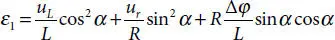
The radial strain is derived as:
(3.6) 
Therefore, the internal work can be expressed as these two parts above adding together:
(3.7) 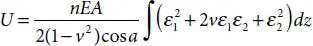
Similarly, the stiffness matrix of helix layers can be derived:
(3.8) 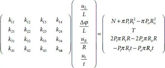
3.2.3 The Stiffness Matrix of Pipe as a Whole Helix Layers
Subjected to the axisymmetric load, all layers at all cross-sections present the same twist per unit of pipe length and the same elongation see Figure 3.3. It will be assumed that all layers of the pipe are numbered consecutively from 1 (the innermost layer) to N (the outermost layer), where N is the total number of layers of the pipe. Combine the stiffness matrix together, Eqs. (3.9)to (3.12)are derived:
(3.9) 
(3.10) 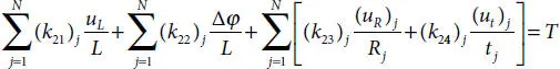
(3.11) 
(3.12) 
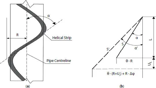
Figure 3.3 Helix mathematical parameters definition.
Still, lacking of equations for solving all unknown variables, the consistent in the radial direction is added to solve the problem:
(3.13) 
where j denotes the layer number. For some applications, the calculated contact pressure between layers may be found negative. Treating such a case requires a change of unknowns. The contact pressure is known and equal to zero and the gap between the two layers becomes the new unknown.
3.2.4 Blasting Failure Criterion
In order to use the above method to predict the burst pressure of flexible pipe, it is necessary to introduce the failure criterion into the program. API17J [9] stipulates that the bearing capacity of the structure can be determined by the yield strength of the material or 0. 9 times of the ultimate tensile strength. In order to simulate the properties of steel used in practice, the Ramberg-Osgood model expressed in Eq. (3.14)is used to describe the non-linear stress-strain relationship of the armor layers. For this model, the pressure armor’s ultimate strength is 630 MPa.
(3.14) 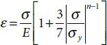
Where σy = 600MPa, E = 207GPa, n = 13.
Specifically, the total load is decomposed into a limited increment for loading. Attention should be paid to the step size of the incremental step is small enough to ensure the convergence of the results. In this chapter, Mises stress is used as failure criterion. When Mises stress reaches ultimate strength during loading, it is considered that the pressure armor failures.
3.3 FEA Modeling Description
In this chapter, ABAQUS model is used to verify the correction of theoretical model. The finite element model consists of a Z-type self-locking pressure armor layer, two layers of tension armor layer with opposite winding angles and other polymer layers. Specific size information is shown below in Table 3.1, Table 3.2.
As the structure of the model is quite complex and there are a lot of contact between layers, implicit static analysis is not only time-consuming but also brings a lot of convergence problems. Therefore, this chapter uses dynamic explicit method to carry out the analysis. Due to the non-bonding between the layers of flexible pipe, contact and slip might occur between the layers during the loading process and self-contact will occur in the pressure armor layer, which makes the contact situation more complex. Therefore, the “All with itself” algorithm is used to simulate contact in the ABAQUS model. This algorithm can automatically identify contact pairs and can consider the possible layer separation. The contact normal direction is set by hard contact, and the tangential direction is set by non-friction.
Table 3.1 Geometric and material parameters of FEM.
| Layer name | Parameters |
|---|---|
| 1. Pressure sheath | Internal radius: 76 mmThickness: 6 mmYoung modulus: 1,040 MpaPoisson ratio: 0.45Thickness: 10 mmNumber of wires: 1 |
| 2. Pressure armor | Profile: shown in Figure 3.4Winding angle: +88.8° Young modulus: 207,000 Mpa Poisson ratio: 0.3 Thickness: 1.5 mm |
| 3. Anti-wear tape | Young modulus: 301 MpaPoisson ratio: 0.45Thickness: 5 mmNumber of wires: 46Profile: 5 mm × 11 mm |
| 4. Tensile armor | Winding angle: +54.7°Young modulus: 207,000 MpaPoisson ratio: 0.3Thickness: 1.5 mm |
| 5. Anti-wear tape | Young modulus: 301 MpaPoisson ratio: 0.45Thickness: 5 mmNumber of wires: 47Profile: 5 mm × 11 mm |
| 6. Tensile armor | Winding angle: −54.7°Young modulus: 207,000 MpaPoisson ratio: 0.3Thickness: 4 mm |
| 7. Outer plastic | Young modulus: 1,040 MpaPoisson ratio: 0.45 |
In order to control the boundary conditions of the model conveniently, two reference point (RP-1 and RP-2) are set at the center of the cross-section at both ends of the model. Kinematic coupling which is shown in Figure 3.5is set up between all degrees of freedom of each layer in the cross-section with the reference point. The constraints on the end face are imposed at two reference points (RP-1 and RP-2). All degrees of freedom on RP-1 are constrained, and the torsional direction of RP-2 along z axis is also constrained.
Table 3.2 Pressure armor layer geometrical properties.
| Internal diameter | 164 mm |
| Cross section area (profile) | 102.53 mm 2 |
| Minimum moment of inertia (profile) | 79.67 mm 4 |
| Pitch | 11.87 mm |
| Thickness of the profile | 10 mm |
| Length of the profile | 18.50 mm |

Figure 3.4 Pressure armor cross section profile.
Читать дальшеИнтервал:
Закладка:
Похожие книги на «Deepwater Flexible Risers and Pipelines»
Представляем Вашему вниманию похожие книги на «Deepwater Flexible Risers and Pipelines» списком для выбора. Мы отобрали схожую по названию и смыслу литературу в надежде предоставить читателям больше вариантов отыскать новые, интересные, ещё непрочитанные произведения.


Обсуждение, отзывы о книге «Deepwater Flexible Risers and Pipelines» и просто собственные мнения читателей. Оставьте ваши комментарии, напишите, что Вы думаете о произведении, его смысле или главных героях. Укажите что конкретно понравилось, а что нет, и почему Вы так считаете.