Microgrid Technologies
Здесь есть возможность читать онлайн «Microgrid Technologies» — ознакомительный отрывок электронной книги совершенно бесплатно, а после прочтения отрывка купить полную версию. В некоторых случаях можно слушать аудио, скачать через торрент в формате fb2 и присутствует краткое содержание. Жанр: unrecognised, на английском языке. Описание произведения, (предисловие) а так же отзывы посетителей доступны на портале библиотеки ЛибКат.

- Название:Microgrid Technologies
- Автор:
- Жанр:
- Год:неизвестен
- ISBN:нет данных
- Рейтинг книги:5 / 5. Голосов: 1
-
Избранное:Добавить в избранное
- Отзывы:
-
Ваша оценка:
Microgrid Technologies: краткое содержание, описание и аннотация
Предлагаем к чтению аннотацию, описание, краткое содержание или предисловие (зависит от того, что написал сам автор книги «Microgrid Technologies»). Если вы не нашли необходимую информацию о книге — напишите в комментариях, мы постараемся отыскать её.
Many aspects of microgrids are discussed in this volume, including, in the early chapters of the book, the various types of energy storage systems, power and energy management for microgrids, power electronics interface for AC & DC microgrids, battery management systems for microgrid applications, power system analysis for microgrids, and many others.
The middle section of the book presents the power quality problems in microgrid systems and its mitigations, gives an overview of various power quality problems and its solutions, describes the PSO algorithm based UPQC controller for power quality enhancement, describes the power quality enhancement and grid support through a solar energy conversion system, presents the fuzzy logic-based power quality assessments, and covers various power quality indices.
The final chapters in the book present the recent advancements in the microgrids, applications of Internet of Things (IoT) for microgrids, the application of artificial intelligent techniques, modeling of green energy smart meter for microgrids, communication networks for microgrids, and other aspects of microgrid technologies.
Valuable as a learning tool for beginners in this area as well as a daily reference for engineers and scientists working in the area of microgrids, this is a must-have for any library.
Microgrid Technologies — читать онлайн ознакомительный отрывок
Ниже представлен текст книги, разбитый по страницам. Система сохранения места последней прочитанной страницы, позволяет с удобством читать онлайн бесплатно книгу «Microgrid Technologies», без необходимости каждый раз заново искать на чём Вы остановились. Поставьте закладку, и сможете в любой момент перейти на страницу, на которой закончили чтение.
Интервал:
Закладка:
Figure 2.18shows the load voltage profile when the system is under intentional islanding condition. A healthy working condition between 0.0 and 1.0 s, the load voltage observed as 1 pu. A three-phase to ground fault initiated between 1.0 and 1.5 s. A sudden drop in voltage occurs at 1.0 s and then a spike due to intentional islanding is seen at the instant of 1.0 s. After the occurrence of fault at 1.02 s generator at bus number 3 and load at the bus no. 5 get islanded from the main system. During islanding conditions (i.e. between 1.02 and 1.5 s), the load voltage rises to 1.25 pu. The load voltage becomes normal to 1.0 pu when the islanded part of the system reconnected with the main system at 1.5 s and remains at 1.0 pu till t = 2.0 s.
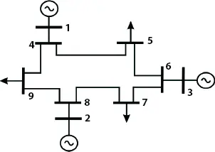
Figure 2.16 IEEE 9 bus system.
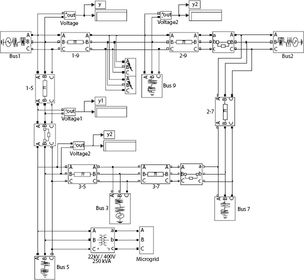
Figure 2.17 IEEE 9 bus test system MATLAB simulation model.
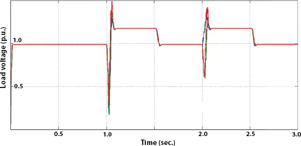
Figure 2.18 Load voltage profile in test case-1.
During the single-phase to ground fault (i.e. between 2.0 and 2.5 s), the load voltage rises to 1.25 pu due to the intentional islanding of the generator at the bus no. 3 and load at the bus no. 5. The voltage profile improves due to the islanding of a balanced system.
2.5.3.2 Test Case: 2—Without GUPFC and With Fuel Cell
Figure 2.19shows an improved load voltage profile compared to similar intentional islanding conditions described in Section 2.5.3.1. During three-phase to ground fault (i.e. between 1.0 and 1.5 s), a voltage spike observed at the switching of intentional islanding of load at an instant of 1.0 s. The load voltage settles to 0.95 pu thereafter during the three-phase fault. The load voltage attains 1 pu during the healthy condition during 1.5 to 2.0 sec.
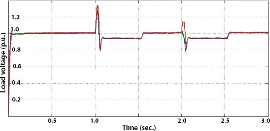
Figure 2.19 Load voltage profile in test case-2.
At 2.0 s phase to ground fault occurs on phase A. The voltage spike is encountered at this instant due to switching of intentional islanding. During the single-phase to ground fault (i.e. between 2.0 and 2.5 s), the load voltage is around 0.95 pu. After clearing of single-phase to ground fault, the load voltage becomes 1 pu.
2.5.3.3 Test Case: 3—With GUPFC and Without Fuel Cell
Figure 2.20shows the load voltage profile in intentional islanding condition with GUPFC and without fuel cell. At normal healthy working conditions between 0.0 and 1.0 s, the load voltage observed around 1 pu. A three-phase to ground fault observed between 1.0 and 1.5 s. After the occurrence of fault at 1.02 s generator at the bus no. 3 and load at the bus no. 5 get islanded from the main system. A spike due to switching seen at the instant of 1.0 s. During islanding conditions (i.e. between 1.02 and 1.5 s), the load voltage rises to around 1.1 pu. The load voltage gets normalized to 1 pu when islanded part of the system reconnected with the main system (i.e. between 1.5 and 2.0 s) During the single-phase to ground fault (i.e. between 2.0 and 2.5 s), the load voltage rises to around 1.1 pu due to the intentional islanding of the generator at the bus no. 3 and a load at the bus no. 5. The voltage profile improves due to the islanding of a balanced system.
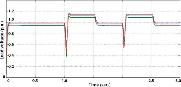
Figure 2.20 Load voltage profile in test case-3.
2.5.3.4 Test Case: 4—With GUPFC and With Fuel Cell
As shown in Figure 2.21with GUPFC and fuel cell in the system under intentional islanding condition, load voltage observed is 1 pu with a healthy system (i.e. between 0.0 and 1.0 s). A brief spike due to switching observed at the instant of fault (i.e. at 1.0 s). The load voltage rises to around 1.1 pu during three-phase to a ground fault between 1.0 and 1.5 s but minor unbalance is observed. The improvement in the load voltage is due to the presence of fuel cells and GUPFC. After clearing of the fault at 1.5 s the load voltage becomes normalized to 1 pu.
The load voltage again rises to 1.1 pu and remains constant during the single-phase to ground fault (i.e. during 2.0 to 2.5 s) with a brief switching spike at the instant of 2.0 s. After clearing of the fault, the load voltage becomes normalized to 1 pu.
2.5.3.5 Test Case: 5—With Active GUPFC
Figure 2.22shows the load voltage profile with an active GUPFC based sub-system. The load voltage remains constant during the entire simulation period. The intentionally islanded load has almost constant voltage. The brief spikes observed during switching in the system at 1.0 and 2.0 s. The fuel cell embedded GUPFC improves the load voltage profile during the three-phase to ground fault and single-phase to ground fault. The GUPFC, as compared to previous test cases, receives power for improving load voltage profile during fault due to fuel cell connected to its common DC bus. The load voltage profile using active GUPFC during intentional islanding condition shows almost constant load voltage of 1 pu during the simulation.
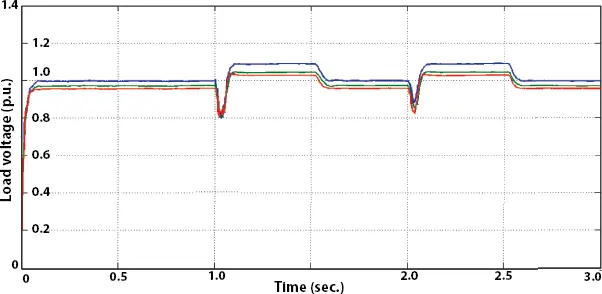
Figure 2.21 Load voltage profile in test case-4.
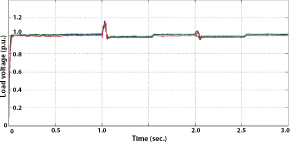
Figure 2.22 Load voltage profile in test case-5.
By examining different test cases, it can be seen that load voltage remains constant with active GUPFC. The percentage load voltage deviation from the rated load voltage calculated as:
(2.19) 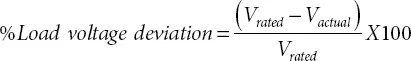
Figure 2.23illustrates the graph of percentage load voltage deviation from the rated value of 1 pu in line to ground fault and Figure 2.24illustrates for three-phase to ground fault.
The observations are listed below:
1 The system without GUPFC and without fuel cell shows maximum percentage deviation of load voltage under the non-islanding condition and intentional islanding connection with rated load voltage of 1 pu. It observed that the percentage variation in intentional islanding conditions is less than that of non-islanded conditions.
2 The system without GUPFC and with fuel cell shows improvement in the load voltage profile in intentionalislanding connection but fails to maintain load voltage profile with the non-islanding condition during the fault. Figure 2.23 Summary of simulation: Percentage load voltage deviation from rated value for line to ground fault. Figure 2.24 Summary of simulation: Percentage load voltage deviation from rated value for three phase to ground fault.
Читать дальшеИнтервал:
Закладка:
Похожие книги на «Microgrid Technologies»
Представляем Вашему вниманию похожие книги на «Microgrid Technologies» списком для выбора. Мы отобрали схожую по названию и смыслу литературу в надежде предоставить читателям больше вариантов отыскать новые, интересные, ещё непрочитанные произведения.


Обсуждение, отзывы о книге «Microgrid Technologies» и просто собственные мнения читателей. Оставьте ваши комментарии, напишите, что Вы думаете о произведении, его смысле или главных героях. Укажите что конкретно понравилось, а что нет, и почему Вы так считаете.