Microgrid Technologies
Здесь есть возможность читать онлайн «Microgrid Technologies» — ознакомительный отрывок электронной книги совершенно бесплатно, а после прочтения отрывка купить полную версию. В некоторых случаях можно слушать аудио, скачать через торрент в формате fb2 и присутствует краткое содержание. Жанр: unrecognised, на английском языке. Описание произведения, (предисловие) а так же отзывы посетителей доступны на портале библиотеки ЛибКат.
- Название:Microgrid Technologies
- Автор:
- Жанр:
- Год:неизвестен
- ISBN:нет данных
- Рейтинг книги:5 / 5. Голосов: 1
-
Избранное:Добавить в избранное
- Отзывы:
-
Ваша оценка:
Microgrid Technologies: краткое содержание, описание и аннотация
Предлагаем к чтению аннотацию, описание, краткое содержание или предисловие (зависит от того, что написал сам автор книги «Microgrid Technologies»). Если вы не нашли необходимую информацию о книге — напишите в комментариях, мы постараемся отыскать её.
Many aspects of microgrids are discussed in this volume, including, in the early chapters of the book, the various types of energy storage systems, power and energy management for microgrids, power electronics interface for AC & DC microgrids, battery management systems for microgrid applications, power system analysis for microgrids, and many others.
The middle section of the book presents the power quality problems in microgrid systems and its mitigations, gives an overview of various power quality problems and its solutions, describes the PSO algorithm based UPQC controller for power quality enhancement, describes the power quality enhancement and grid support through a solar energy conversion system, presents the fuzzy logic-based power quality assessments, and covers various power quality indices.
The final chapters in the book present the recent advancements in the microgrids, applications of Internet of Things (IoT) for microgrids, the application of artificial intelligent techniques, modeling of green energy smart meter for microgrids, communication networks for microgrids, and other aspects of microgrid technologies.
Valuable as a learning tool for beginners in this area as well as a daily reference for engineers and scientists working in the area of microgrids, this is a must-have for any library.
Microgrid Technologies — читать онлайн ознакомительный отрывок
Ниже представлен текст книги, разбитый по страницам. Система сохранения места последней прочитанной страницы, позволяет с удобством читать онлайн бесплатно книгу «Microgrid Technologies», без необходимости каждый раз заново искать на чём Вы остановились. Поставьте закладку, и сможете в любой момент перейти на страницу, на которой закончили чтение.
Интервал:
Закладка:
65. Mondal, A., Misra, S., Patel, L.S., Pal, S.K., Obaidat, M.S., DEMANDS: Distributed energy management using noncooperative scheduling in smart grid, IEEE Syst. J. , 2018.
1 *Corresponding author: kumarasanjay@gmail.com
2
Power and Energy Management in Microgrid
Jayesh J. Joglekar
MIT World Peace University, Pune, India
Abstract
The microgrid voltage management has a significant concern during unstable system condition due to limited power to frequency ratio (MW/Hz). The selection of sources for microgrid would play an essential role and power management techniques could save the microgrid from the complete blackout. The modification in the power flow controller could achieve desirable results with an appropriate position of the power flow controller.
Keywords: BESS, fuel cell, energy storage, microgrid, renewable source
2.1 Introduction
The power system in the modern world is restructured based on source, nature of load and geographical space availability. The grid size also depends on the need of society and consumers. The concept of microgrid (MG) emerges from the traditional grid. But like the traditional grid, MG has a limited area to serve and hence the transmission lines could be replaced by underground cables. Depending on the application at the consumer end, MG could be with Alternating Current or with Direct Current or mixed one. Due to limited size, capacity and consumer base, power flow in MG could be a critical issue. For the interconnected AC transmission line network, transfer capacity is an economical operational constraint. It forces to use the available infrastructure to its maximum limit. The increased usability of the transmission limit handled by the FACTS controllers. These controllers are known for their applications in improving power transfer capacity as well as stability using the existing infrastructure of a transmission utility. In addition to transmission capacity enhancement and power flow control, FACTS controllers have other advantages like transient stability improvement, power oscillation damping, voltage stability and control. The transmission line capacity is enhanced by around 40 to 50% by installing a FACTS controller in comparison to conventional mechanically-driven devices, as FACTS controllers are not subject to wear and tear and require a lower maintenance [1].
2.2 Microgrid Structure
The Microgrid (MG) broadly comprises of source, load and controller, as shown in Figure 2.1. The choice of the source depends on the geographical location of MG and the type as well as the demand of the load. The emerging technologies such as fuel cell could be suitable for supplying the base load and proves advantageous over batteries. The working of a fuel cell is similar to the battery. The batteries contain the limited capacity of support chemicals. They have a fixed life cycle, but a fuel cell is supplied with fuel externally and operates continuously as long as fuel supplied. An electrolyte separates an anode and a cathode in the fuel cell. The type of fuel cell decided by electrolyte used. A fuel cell is a static energy converter from chemical to electrical energy. It is a modular, efficient and very low emission power source for a distributed system. It is clear that fuel cell is an upcoming option for conventional power generation resources [2–5]. Fuel cell produces electricity from external supplies of hydrogen fuel (on the anode side) and oxidant (on the cathode side) in the presence of an electrolyte. Generally, the reactants flow in and reaction products flow out while the electrolyte remains in the cell. Fuel cells can operate almost continuously as long as the necessary fuel flows are maintained. There are different types of fuel cell based on base chemical or membrane used. Those are Phosphoric Acid Fuel Cell (PAFC), Solid Oxide Fuel Cell (SOFC), Molten Carbonate Fuel Cell (MCFC) Proton Exchange Membrane Fuel Cell (PEMFC), etc.
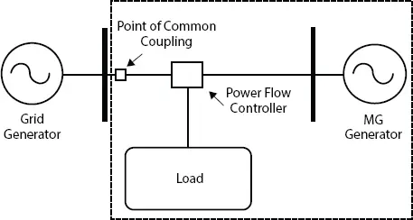
Figure 2.1 Basic structure of microgrid (MG).
2.2.1 Selection of Source for DG
With multiple options available based on technology used, fuel cells became a well-known source of energy in recent years. The selection of fuel cell is broadly based on the type of application it performs. Table 2.1shows comparison of present fuel cell technologies and suitable applications. The fuel cell is an upcoming option for power generation and hybrid power system. It ensures a reliable green power. A variety of fuel cell technologies exist and out of them, PAFC is found suitable for distributed generation.
2.2.1.1 Phosphoric Acid Fuel Cell (PAFC)
This fuel cell is a matured in technology and commercially available. PAFC has platinum or platinum alloys used as the catalyst at both electrodes. The stack consists of a repeating arrangement of anode and cathode. As the freezing point of phosphoric acid (H 3PO 4) is 40 °C, the PAFC must be kept above this temperature once commissioned, to avoid the thermal stresses. For PAFC, water cooling is used for larger power generation systems [6, 7]. The operating current densities are 150 to 400 mA/cm. The operating cell voltages are 600–800 mV. The ohmic losses in PAFC are quite small. The ability of PAFC to sustain impurity and its voltage–current and power–current characteristics makes it highly suitable for micro-grid. Figure 2.2shows typical characteristic of PAFC plotted for 1 kW stack. Figure 2.3shows the average cell voltage vs current density of PAFC after testing for 50 and 250 h [2].
2.2.1.2 Mathematical Modeling of PAFC Fuel Cell
The output voltage of fuel cell is given by Nernst equation as [8–11]:
(2.1) 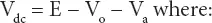
Table 2.1 Fuel cell resource comparison (courtesy: DOE, US Government).
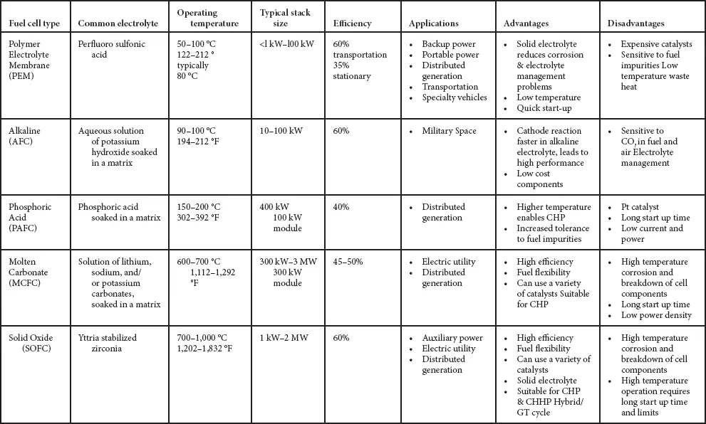
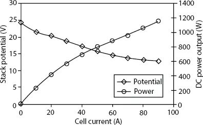
Figure 2.2 PAFC characteristics.
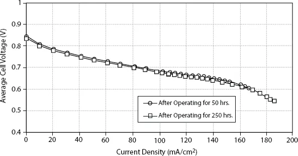
Figure 2.3 PAFC average cell voltage vs current density.
Where:
V dc= Fuel cell output voltage (Volt)
E = Thermodynamic potential of fuel cell (Volt) which is expressed by:
(2.2) 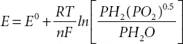
E 0= Potential of unit cavity in fuel cell = 1.229 V
PH 2, PO 2& PH 2O = Particle pressure of Hydrogen, Oxygen and vapor (atm)
T = Cell temperature (K)
R = Universal gas constant = 8.31441 J/mol-K
F = Faraday constant = 94,685 C/mol
n = Number of electrons participating in the reaction
V 0= Ohmic voltage drop (Volt) which is given by:
(2.3) 
Интервал:
Закладка:
Похожие книги на «Microgrid Technologies»
Представляем Вашему вниманию похожие книги на «Microgrid Technologies» списком для выбора. Мы отобрали схожую по названию и смыслу литературу в надежде предоставить читателям больше вариантов отыскать новые, интересные, ещё непрочитанные произведения.


Обсуждение, отзывы о книге «Microgrid Technologies» и просто собственные мнения читателей. Оставьте ваши комментарии, напишите, что Вы думаете о произведении, его смысле или главных героях. Укажите что конкретно понравилось, а что нет, и почему Вы так считаете.