Microgrid Technologies
Здесь есть возможность читать онлайн «Microgrid Technologies» — ознакомительный отрывок электронной книги совершенно бесплатно, а после прочтения отрывка купить полную версию. В некоторых случаях можно слушать аудио, скачать через торрент в формате fb2 и присутствует краткое содержание. Жанр: unrecognised, на английском языке. Описание произведения, (предисловие) а так же отзывы посетителей доступны на портале библиотеки ЛибКат.
- Название:Microgrid Technologies
- Автор:
- Жанр:
- Год:неизвестен
- ISBN:нет данных
- Рейтинг книги:5 / 5. Голосов: 1
-
Избранное:Добавить в избранное
- Отзывы:
-
Ваша оценка:
Microgrid Technologies: краткое содержание, описание и аннотация
Предлагаем к чтению аннотацию, описание, краткое содержание или предисловие (зависит от того, что написал сам автор книги «Microgrid Technologies»). Если вы не нашли необходимую информацию о книге — напишите в комментариях, мы постараемся отыскать её.
Many aspects of microgrids are discussed in this volume, including, in the early chapters of the book, the various types of energy storage systems, power and energy management for microgrids, power electronics interface for AC & DC microgrids, battery management systems for microgrid applications, power system analysis for microgrids, and many others.
The middle section of the book presents the power quality problems in microgrid systems and its mitigations, gives an overview of various power quality problems and its solutions, describes the PSO algorithm based UPQC controller for power quality enhancement, describes the power quality enhancement and grid support through a solar energy conversion system, presents the fuzzy logic-based power quality assessments, and covers various power quality indices.
The final chapters in the book present the recent advancements in the microgrids, applications of Internet of Things (IoT) for microgrids, the application of artificial intelligent techniques, modeling of green energy smart meter for microgrids, communication networks for microgrids, and other aspects of microgrid technologies.
Valuable as a learning tool for beginners in this area as well as a daily reference for engineers and scientists working in the area of microgrids, this is a must-have for any library.
Microgrid Technologies — читать онлайн ознакомительный отрывок
Ниже представлен текст книги, разбитый по страницам. Система сохранения места последней прочитанной страницы, позволяет с удобством читать онлайн бесплатно книгу «Microgrid Technologies», без необходимости каждый раз заново искать на чём Вы остановились. Поставьте закладку, и сможете в любой момент перейти на страницу, на которой закончили чтение.
Интервал:
Закладка:
I = Cell current (Amp)
R int= Internal resistance between electrodes which is given by:
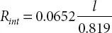
l = Length between two electrodes (Meter)
V a= Summation of activation voltage drop and concentration voltage drop (Volt) which is expressed by:
(2.4) 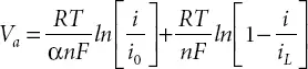
α = Electron transfer co-efficient
i = Current density (A/m 2)
i 0= Exchange current density (A/m 2)
i L= Limiting current density (A/m 2)

є = Electrical permittivity of electrolyte
A = Effective surface area between electrodes and electrolyte (sq. meter). It is very large due to corrugated porous surface of the electrodes.
l = Distance between two layers of electrodes. It is very small (nanometer).
V C= Voltage across the Capacitor ‘C’. It is given by:
(2.5) 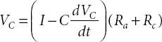
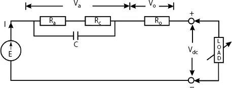
Figure 2.4 PAFC equivalent circuit.
There are three operating regions for this fuel cell. The first region is activation region where the voltage drop is due to the slowness of the chemical reactions at electrode. It is considered as R a. The second region represents the ohmic losses due to the internal resistance of the fuel cell. It is represented by R o. The third region represents the change in concentration of reactants as the fuel is used. It is represented by R c. By considering these three operating regions of fuel cell, an equivalent DC circuit model is obtained as shown in Figure 2.4.
2.3 Power Flow Management in Microgrid
The transfer capacity of the existing transmission lines is an important operational constraint on interconnected A.C. transmission network. To improve this capacity of the transmission line, one has to use the FACTS controllers. These controllers are known for their applications in improving power transfer capacity and power flow control using the existing infrastructure of a transmission utility as well as improving transient stability. In addition to these controls, FACTS controllers advantageously employed for transient stability improvement, power oscillation damping and voltage stability. With the FACTS controller, the transmission line capacity can be improved by 40 to 50% as compared to conventional mechanically-driven devices. Lower maintenance required for FACTS controllers improves effi-ciency in operation [1].
The FACTS controllers connected to the transmission line have following basic types depending on connection:
1 Series controllers:It has variable impedance and has a function to inject series voltage.
2 Shunt controllers:It has variable impedance and has a function to inject current in the system.
3 Combined series–series controller:It has separate but coordinated unified (common DC bus) controllers and can compensate reactive power as well as interline transfer active power.
4 Combined series–shunt controller:It can inject voltage and current and has unified and coordinated real power exchange between series and shunt controllers.
The UPFC, as shown in Figure 2.5, invented in 1991, is a real-time multi-functional dynamic compensator for the AC transmission line. It can control active and reactive power as well as voltage and VAR compensation. It also can improve the power quality of the associated system. Thus UPFC can control output voltage V oand its angle ρ (0 ≤ ρ ≤ 2π) [1]. The operation of UPFC depends on types of voltage source converters. The shunt converter is Static Compensator (STATCOM) and series compensator is Static Synchronous Series Compensator (SSSC) [1]. The STATCOM is a static, shunt connected compensator which can control current independent of system voltage with the help of capacitor or inductor. In UPFC, capacitor-based current compensation considered. Hence depending on the system requirement, leading current can be injected in the system with the help of a capacitor connected to the common DC bus. It absorbs active power for charging the capacitor. So it has the role of Static Synchronous Generator (SSG) and Static VAR Generator (SVG). The SSSC is a series-connected compensator which can control series injected voltage. The magnitude of the series injected voltage is low. Still, the converter can change the voltage angle regarding sending end voltage, resulting in a change in receiving end voltage magnitude and angle depending on the system requirements.
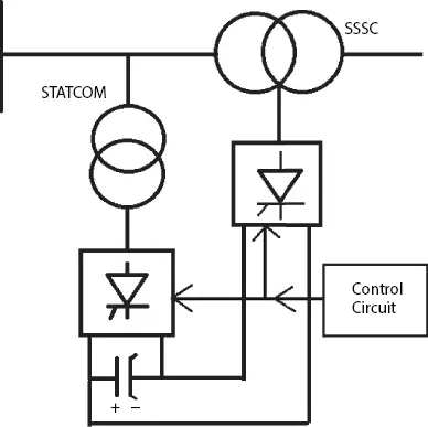
Figure 2.5 Basic UPFC.
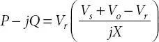
If the compensator connected with the energy storage capacitor, then it can absorb active power too. The transmitted power P and reactive power −jQ can be expressed by:
2.4 Generalized Unified Power Flow Controller (GUPFC)
The basic circuit of a GUPFC developed by Fardanesh in the year 2000 is shown in Figure 2.6. It inferred from the figure that it is a combination of UPFC and Interline Power Flow Controller (IPFC). There is one shunt connected converter (STATCOM) and multiple series-connected converters (SSSC). The series converters and shunt converter are connected to a common capacitor to form the DC bus. The shunt converters and the series converters act as a synchronous voltage source (SVS). These converters can generate reactive power at their terminals. Free exchange of real power is possible because of common DC link. The real power demand is fulfilled by shunt converter, which at the same time can absorb or supply controllable reactive power and exchange the same with series converters. The series converters can individually inject a voltage to the appropriately connected feeder whose magnitude and phase angle can be varied to obtain the desired voltage output. Thus the series converters act as a series compensation device. It means that the overloaded feeder lines can be balanced and any surplus power utilized by other feeders or common DC link [1, 12, 13].
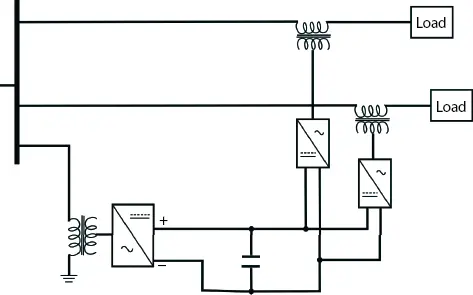
Figure 2.6 Basic GUPFC.
2.4.1 Mathematical Modeling of GUPFC
The basic circuit shown in Figure 2.6is considered here for modeling. The development is based on the fundamental frequency model of UPFC which is presented in Refs. [14] and [15]. The basic concept of UPFC has briefly explained already in this section. Modeling aims to determine the relationship between unified DC bus voltage and injected voltage. A three-phase, PWM controlled voltage source inverter is typically made of six controlled switches (GTO valves with six anti-parallel diodes) switched on and off at very high frequency around 5 kHz. The model considered a stable voltage condition for fundamental frequency voltage sources. One source is connected in parallel while the other connected in a series branch.
Читать дальшеИнтервал:
Закладка:
Похожие книги на «Microgrid Technologies»
Представляем Вашему вниманию похожие книги на «Microgrid Technologies» списком для выбора. Мы отобрали схожую по названию и смыслу литературу в надежде предоставить читателям больше вариантов отыскать новые, интересные, ещё непрочитанные произведения.


Обсуждение, отзывы о книге «Microgrid Technologies» и просто собственные мнения читателей. Оставьте ваши комментарии, напишите, что Вы думаете о произведении, его смысле или главных героях. Укажите что конкретно понравилось, а что нет, и почему Вы так считаете.