Microgrid Technologies
Здесь есть возможность читать онлайн «Microgrid Technologies» — ознакомительный отрывок электронной книги совершенно бесплатно, а после прочтения отрывка купить полную версию. В некоторых случаях можно слушать аудио, скачать через торрент в формате fb2 и присутствует краткое содержание. Жанр: unrecognised, на английском языке. Описание произведения, (предисловие) а так же отзывы посетителей доступны на портале библиотеки ЛибКат.

- Название:Microgrid Technologies
- Автор:
- Жанр:
- Год:неизвестен
- ISBN:нет данных
- Рейтинг книги:5 / 5. Голосов: 1
-
Избранное:Добавить в избранное
- Отзывы:
-
Ваша оценка:
Microgrid Technologies: краткое содержание, описание и аннотация
Предлагаем к чтению аннотацию, описание, краткое содержание или предисловие (зависит от того, что написал сам автор книги «Microgrid Technologies»). Если вы не нашли необходимую информацию о книге — напишите в комментариях, мы постараемся отыскать её.
Many aspects of microgrids are discussed in this volume, including, in the early chapters of the book, the various types of energy storage systems, power and energy management for microgrids, power electronics interface for AC & DC microgrids, battery management systems for microgrid applications, power system analysis for microgrids, and many others.
The middle section of the book presents the power quality problems in microgrid systems and its mitigations, gives an overview of various power quality problems and its solutions, describes the PSO algorithm based UPQC controller for power quality enhancement, describes the power quality enhancement and grid support through a solar energy conversion system, presents the fuzzy logic-based power quality assessments, and covers various power quality indices.
The final chapters in the book present the recent advancements in the microgrids, applications of Internet of Things (IoT) for microgrids, the application of artificial intelligent techniques, modeling of green energy smart meter for microgrids, communication networks for microgrids, and other aspects of microgrid technologies.
Valuable as a learning tool for beginners in this area as well as a daily reference for engineers and scientists working in the area of microgrids, this is a must-have for any library.
Microgrid Technologies — читать онлайн ознакомительный отрывок
Ниже представлен текст книги, разбитый по страницам. Система сохранения места последней прочитанной страницы, позволяет с удобством читать онлайн бесплатно книгу «Microgrid Technologies», без необходимости каждый раз заново искать на чём Вы остановились. Поставьте закладку, и сможете в любой момент перейти на страницу, на которой закончили чтение.
Интервал:
Закладка:
The series converters are injecting voltage and hence in the equivalent diagram in Figure 2.7it is represented with voltage source and modeling is also based on this assumption [16]. The instantaneous power flowing into shunt inverter from AC bus, neglecting transformer losses and assuming balancing conditions with fundamental frequency, can be represented by:
(2.6) 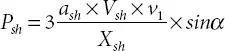
Where,
(2.7a) 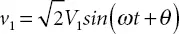
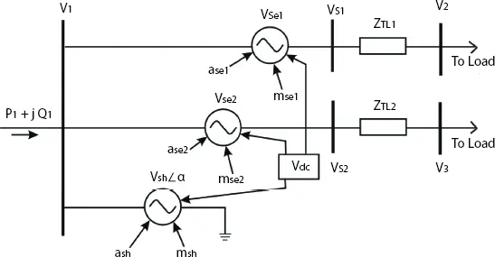
Figure 2.7 GUPFC equivalent circuit.
(2.7b) 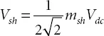
(2.7c) 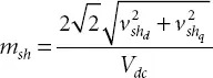
(2.7d) 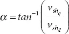
This model consists of two voltage sources. These voltage sources are gained from inverters connected in series and parallel. Hence amplitude modulation factors are used to calculate voltage source magnitudes as:
(2.8) 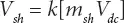
(2.9) 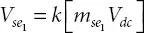
(2.10) 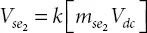
Where,
k = constant based on type of inverter (for six pulse converter

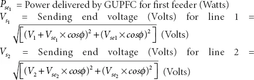
The power delivered by GUPFC in steady state is given by:
(2.11) 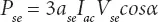
Where,
(2.12a) 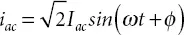
(2.12b) 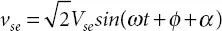
(2.12c) 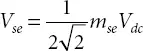
Using line impedance for calculating voltage as shown in Equation (2.6), Equation (2.11)can be rewritten as:
(2.13) 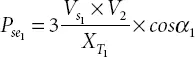
and
(2.14) 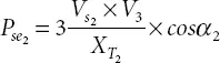
Where,
The resulting equation of GUPFC is considered using Equations (2.10)to (2.14)for finding out factors on which injected power depends. The resulting equation has the form given below:
(2.15) 
Equation (2.15)is true only if ash , ase , msh , mse , XT remain constant. It can be seen that series injected power by the GUPFC is controlled by DC voltage (V dc) and phase angle difference between V 1and V se1(α). This means the sub-system voltage control depends on two quantities (i.e. V dcand α).
2.5 Active GUPFC
The use of two SSSCs in Generalized Unified Power Flow Controller (GUPFC) is aimed at controlling active as well as reactive power. In the proposed method, GUPFC installed for the same purpose by employing active sources like fuel cells to the common DC bus instead of BESS. The system shown in Figure 2.8where the fuel cell is embedded with GUPFC in sub-system to ensure uninterrupted supply under all fault conditions.
The heavily loaded feeders get relaxation due to impedance control and voltage profile improvement after implementation of the proposed method. The dependability of generating stations on grid power for supplying auxiliaries will be considerably reduced with improved power quality at load side with or without grid connectivity when fed with active GUPFC based sub-system [17]. Figure 2.9shows the general outline of the proposed system.
In reasonable working conditions as sub-system sources float, the main grid supplies power to sub-system loads based on demand. Whenever there is a grid disturbance and the main grid is unable to provide additional power to the sub-system, it has to separate from the main grid at a point of common coupling (PCC). The sub-system continues supplying power to the auxiliary system of generating stations. Figure 2.10shows the condition when subsystem source i.e., DG embedded GUPFC fulfils the demand of auxiliaries.
The proposed method is an application for generating stations. In this research work, thermal generating stations considered as it has the highest installed capacity in India [3]. Due to the grid disturbance, a generating station, usually, experiences shortfall of power for running auxiliaries. This difficulty is overcome by using the energy from the sub-system. However, the stable operation of the sub-system is also an issue of concern when it has a renewable, nature dependent source. The use of fuel cells can provide an uninterrupted and stable power supply if installed with proper electronic converters.
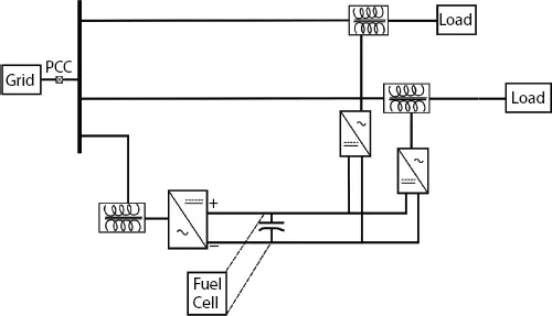
Figure 2.8 Proposed system.
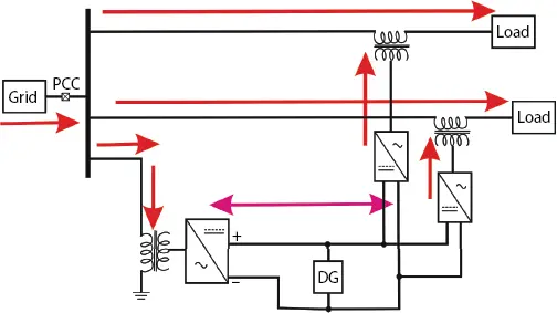
Figure 2.9 Proposed system with grid connection.
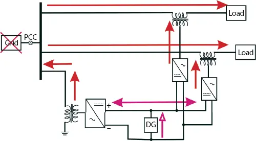
Figure 2.10 Proposed system without grid connection.
2.5.1 Active GUPFC Control System
GUPFC control system consists of the shunt converter control system and series converter control system. This control system based on the vector control approach introduced in [1]. The objective of the control system is to maintain terminal voltage using the shunt converter and injunction of the series voltage vector using the series converter. Depending on the system conditions, the series converter can inject or draw reactive power from the series element. But shunt and series converters do not share reactive power through common DC link. The control function of the shunt converter is divided into two operational modes, as listed below.
Читать дальшеИнтервал:
Закладка:
Похожие книги на «Microgrid Technologies»
Представляем Вашему вниманию похожие книги на «Microgrid Technologies» списком для выбора. Мы отобрали схожую по названию и смыслу литературу в надежде предоставить читателям больше вариантов отыскать новые, интересные, ещё непрочитанные произведения.


Обсуждение, отзывы о книге «Microgrid Technologies» и просто собственные мнения читателей. Оставьте ваши комментарии, напишите, что Вы думаете о произведении, его смысле или главных героях. Укажите что конкретно понравилось, а что нет, и почему Вы так считаете.