Doug Lowe - Networking All-in-One For Dummies
Здесь есть возможность читать онлайн «Doug Lowe - Networking All-in-One For Dummies» — ознакомительный отрывок электронной книги совершенно бесплатно, а после прочтения отрывка купить полную версию. В некоторых случаях можно слушать аудио, скачать через торрент в формате fb2 и присутствует краткое содержание. Жанр: unrecognised, на английском языке. Описание произведения, (предисловие) а так же отзывы посетителей доступны на портале библиотеки ЛибКат.

- Название:Networking All-in-One For Dummies
- Автор:
- Жанр:
- Год:неизвестен
- ISBN:нет данных
- Рейтинг книги:4 / 5. Голосов: 1
-
Избранное:Добавить в избранное
- Отзывы:
-
Ваша оценка:
Networking All-in-One For Dummies: краткое содержание, описание и аннотация
Предлагаем к чтению аннотацию, описание, краткое содержание или предисловие (зависит от того, что написал сам автор книги «Networking All-in-One For Dummies»). Если вы не нашли необходимую информацию о книге — напишите в комментариях, мы постараемся отыскать её.
s covers all the basic and not-so-basic information you need to get a network up and running. It also helps you keep it running as it grows more complicated, develops bugs, and encounters all the fun sorts of trouble you expect from a complex system. Ideal both as a starter for newbie administrators and as a handy quick reference for pros, this book is built for speed, allowing you to get past all the basics—like installing and configuring hardware and software, planning your network design, and managing cloud services—so you can get on with what your network is actually intended to do.
In a friendly, jargon-free style, Doug Lowe—an experienced IT Director and prolific tech author—covers the essential, up-to-date information for networking in systems such as Linux and Windows 10 and clues you in on best practices for security, mobile, and more. Each of the nine minibooks demystifies the basics of one key area of network management.
Plan and administrate your network Implement virtualization Get your head around networking in the Cloud Lock down your security protocols The best thing about this book? You don’t have to read it all at once to get things done; once you’ve solved the specific issue at hand, you can put it down again and get on with your life. And the next time you need it, it’ll have you covered.
Networking All-in-One For Dummies — читать онлайн ознакомительный отрывок
Ниже представлен текст книги, разбитый по страницам. Система сохранения места последней прочитанной страницы, позволяет с удобством читать онлайн бесплатно книгу «Networking All-in-One For Dummies», без необходимости каждый раз заново искать на чём Вы остановились. Поставьте закладку, и сможете в любой момент перейти на страницу, на которой закончили чтение.
Интервал:
Закладка:
The OSI model breaks the various aspects of a computer network into seven distinct layers. These layers are kind of like the layers of an onion: Each successive layer envelops the layer beneath it, hiding its details from the levels above. The OSI model is also like an onion in that if you start to peel it apart to have a look inside, you’re bound to shed a few tears.
The OSI model is not a networking standard in the same sense that Ethernet and TCP/IP are networking standards. Rather, the OSI model is a framework into which the various networking standards can fit. The OSI model specifies what aspects of a network’s operation can be addressed by various network standards. So, in a sense, the OSI model is sort of a standard of standards.
Table 1-1summarizes the seven layers of the OSI model.
TABLE 1-1The Seven Layers of the OSI Model
| Layer | Name | Description |
|---|---|---|
| 1 | Physical | Governs the layout of cables and devices, such as repeaters and hubs. |
| 2 | Data link | Provides Media Access Control (MAC) addresses to uniquely identify network nodes and a means for data to be sent over the physical layer in the form of packets. Bridges and switches are layer 2 devices. |
| 3 | Network | Handles routing of data across network segments. |
| 4 | Transport | Provides for reliable delivery of packets. |
| 5 | Session | Establishes sessions between network applications. |
| 6 | Presentation | Converts data so that systems that use different data formats can exchange information. |
| 7 | Application | Allows applications to request network services. |
The first three layers are sometimes called the lower layers. They deal with the mechanics of how information is sent from one computer to another over a network. Layers 4 through 7 are sometimes called the upper layers. They deal with how application software can relate to the network through application programming interfaces.
The following sections describe each of these layers in greater detail.
 The seven layers of the OSI model are a somewhat idealized view of how networking protocols should work. In the real world, actual networking protocols don’t follow the OSI model to the letter. The real world is always messier. Still, the OSI model provides a convenient — if not completely accurate — conceptual picture of how networking works.
The physical layer
The bottom layer of the OSI model is the physical layer. It addresses the physical characteristics of the network, such as the types of cables used to connect devices, the types of connectors used, how long the cables can be, and so on. For example, Ethernet spells out the exact Layer 1 requirements for twisted-pair cables that can be used at various speeds — 100 Mbps, 1 Gbps, 10 Gbps, and even faster. The star, bus, ring, and mesh network topologies described in Book 1, Chapter 2apply to the physical layer.
Another aspect of the physical layer is the electrical characteristics of the signals used to transmit data over the cables from one network node to another. The physical layer doesn’t define any meaning to those signals other than the basic binary values of 1 and 0. The higher levels of the OSI model must assign meanings to the bits that are transmitted at the physical layer.
One type of physical layer device commonly used in networks is a repeater, which is used to regenerate the signal whenever you need to exceed the cable length allowed by the physical layer standard. In the old days, we used to use physical layer devices called hubs to split an Ethernet segment to multiple devices. Technically, hubs are known as multiport repeaters because the purpose of a hub is to regenerate every packet received on any port on all the hub’s other ports. Repeaters and hubs don’t examine the contents of the packets that they regenerate, though. If they did, they would be working at the data link layer, and not at the physical layer.
The network adapter (also called a network interface card; NIC) installed in each computer on the network is a physical layer device. You can display information about the network adapter (or adapters) installed in a Windows computer by displaying the adapter’s Properties dialog box, as shown in Figure 1-1. To access this dialog box in Windows, open the Control Panel, choose Network and Internet, choose Network and Sharing Center, and then choose Change Adapter Settings. Then right-click the Local Area Connection icon and choose Properties from the menu that appears.
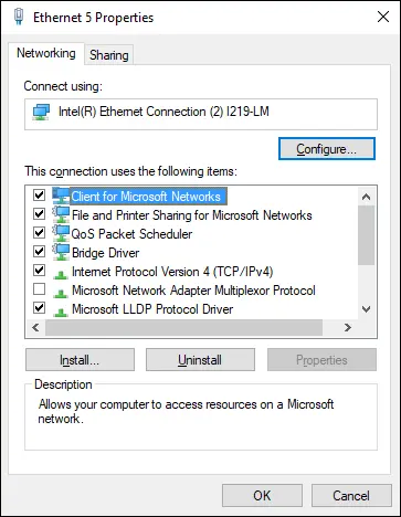
FIGURE 1-1:The Properties dialog box for a network adapter.
 Windows 10 seems to bury some of the most useful settings pages, making them difficult to find. Even the incredibly useful Control Panel can be a chore to find. I suggest you pin the Control Panel to both the Start menu and the taskbar. You can find the Control Panel by pressing the Windows key, typing Control Panel, right-clicking the Control Panel icon, and choosing both Pin to Start and Pin to Taskbar so the Control Panel will always be readily available.
While you’re at it, switch Control Panel from Category view to Small Icons view. This step will eliminate a lot of extra navigation trying to get to the settings pages you need. For example, in Small Icons view, you can go directly from Control Panel to Network and Sharing Center without first having to open the Network and Internet link.
The data link layer
The data link layer is the lowest layer at which meaning is assigned to the bits that are transmitted over the network. Data link protocols address things such as the size of each packet of data to be sent, a means of addressing each packet so that it’s delivered to the intended recipient, and a way to ensure that two or more nodes don’t try to transmit data on the network at the same time.
The data link layer also provides basic error detection and correction to ensure that the data sent is the same as the data received. If an uncorrectable error occurs, the data link standard must specify how the node is to be informed of the error so that it can retransmit the data.
At the data link layer, each device on the network has an address: the MAC address. This address is hard-wired into every network device by the manufacturer. MAC addresses are unique; no two network devices made by any manufacturer anywhere in the world can have the same MAC address.
You can see the MAC address for a computer’s network adapter by opening a command window and running the ipconfig /allcommand, as shown in Figure 1-2. In this example, the MAC address of the network card is A0-8C-FD-D0-E6-2E. (The ipconfigcommand refers to the MAC address as the physical address. )
 One of the most import functions of the data link layer is to provide a way for packets to be sent safely over the physical media without interference from other nodes attempting to send packets at the same time. The two most popular ways to do this are CSMA/CD and token passing. (Take a deep breath. CSMA/CD stands for Carrier Sense Multiple Access/Collision Detection.) Ethernet networks use CSMA/CD, and token ring networks use token passing.
Интервал:
Закладка:
Похожие книги на «Networking All-in-One For Dummies»
Представляем Вашему вниманию похожие книги на «Networking All-in-One For Dummies» списком для выбора. Мы отобрали схожую по названию и смыслу литературу в надежде предоставить читателям больше вариантов отыскать новые, интересные, ещё непрочитанные произведения.


Обсуждение, отзывы о книге «Networking All-in-One For Dummies» и просто собственные мнения читателей. Оставьте ваши комментарии, напишите, что Вы думаете о произведении, его смысле или главных героях. Укажите что конкретно понравилось, а что нет, и почему Вы так считаете.