Liliana Andrade - Multi-Processor System-on-Chip 2
Здесь есть возможность читать онлайн «Liliana Andrade - Multi-Processor System-on-Chip 2» — ознакомительный отрывок электронной книги совершенно бесплатно, а после прочтения отрывка купить полную версию. В некоторых случаях можно слушать аудио, скачать через торрент в формате fb2 и присутствует краткое содержание. Жанр: unrecognised, на английском языке. Описание произведения, (предисловие) а так же отзывы посетителей доступны на портале библиотеки ЛибКат.
- Название:Multi-Processor System-on-Chip 2
- Автор:
- Жанр:
- Год:неизвестен
- ISBN:нет данных
- Рейтинг книги:3 / 5. Голосов: 1
-
Избранное:Добавить в избранное
- Отзывы:
-
Ваша оценка:
Multi-Processor System-on-Chip 2: краткое содержание, описание и аннотация
Предлагаем к чтению аннотацию, описание, краткое содержание или предисловие (зависит от того, что написал сам автор книги «Multi-Processor System-on-Chip 2»). Если вы не нашли необходимую информацию о книге — напишите в комментариях, мы постараемся отыскать её.
Multi-Processor System-on-Chip 2 — читать онлайн ознакомительный отрывок
Ниже представлен текст книги, разбитый по страницам. Система сохранения места последней прочитанной страницы, позволяет с удобством читать онлайн бесплатно книгу «Multi-Processor System-on-Chip 2», без необходимости каждый раз заново искать на чём Вы остановились. Поставьте закладку, и сможете в любой момент перейти на страницу, на которой закончили чтение.
Интервал:
Закладка:
The throughput of channel decoders depends on various communication and implementation parameters. Let N be the block size and R the rate of a channel code. Let I denote the number of iterations that a corresponding (iterative) decoder requires to decode a code block ( I = 1 in the case of a non-iterative decoding algorithm). Let P denote the degree of achievable parallelism. P is defined as the ratio between the operations that are performed in one clock cycle, and the total number of operations necessary to perform one decoding iteration for a complete code block. Note that operation represents the “critical operation” in an algorithm: an operation can be a computation as well as a data transfer. Let f be the clock frequency. Using these parameters, the throughput (in information bits per second) of a FEC architecture can be roughly estimated by [2.1]
[2-1] 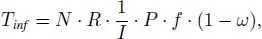
where ω is a normalized value between 0 and 1, that represents the timing overhead due to, for example, data distribution, interconnect, memory access conflicts, etc. The maximum clock frequency f is determined by the critical path in the compute kernels of the corresponding decoding algorithms and/or delay due to interconnect. Moreover, f is typically upper limited to 1 GHz due to power and design methodology constraints. The overhead ω increases with increasing N and P and is larger for decoding algorithms that have limited locality and are data-transfer dominated. The impact of ω on the throughput can be considered as an effective reduction of the clock frequency f or decrease in P , if additional clock cycles are mandatory, for example, due to memory conflicts, that cannot be hidden. If we are targeting 1 Tbit/s throughput with a frequency limit of 1 GHz, 1,000 bits have to be decoded in one single clock cycle that requires extreme parallelism. To achieve the highest throughput, P has to be maximized, and ω minimized. In the following sections, we will discuss the throughput maximization for the different coding schemes.
2.3.1. Turbo decoder
Among the three code classes, Turbo codes are most challenging with respect to high-throughput decoding. The decoding structure consists of two component decoders connected through an interleaver/deinterleaver. These component decoders work cooperatively by exchanging extrinsic information in an iterative loop. The respective bit-wise log-likelihood ratios are computed in a forward and a backward recursion on the trellis in the MAP-based component decoder. Thus, decoding is inherently serial on component decoder (MAP recursions) and on Turbo decoder level (iterative loop). The kernel operation in the MAP is the Add-Compare-Select (ACS) operation. Depending on the encoder’s memory depth, several ACS operations have to be executed to process a single trellis step in the forward and backward recursion, respectively. In total, 4 · K trellis computations and two interleavings have to be performed for one single Turbo decoding iteration. Hence, P is determined by the number of parallel trellis step computations performed by a decoding architecture. The maximum value of P for one decoding iteration, i.e. P = 1, can be achieved by an architecture if the forward/backward recursions of the MAP algorithm are unrolled and pipelined (functional parallelism), yielding the XMAP architecture. P = I if, in addition, iterations are unrolled and pipelined. For a detailed overview and discussion of such highly parallel decoders, we refer to (Weithoffer et al . 2018). Figure 2.2 (left) shows the layout of a Turbo decoder exploiting all levels of parallelism ( P = I ) and an optimized interleaver such that ω is very small (Weithoffer et al . 2018). The decoder achieves 102 Gbit/s information bit throughput for an information block length of 128 bit, on a low Vt 28 nm Fully Depleted Silicon on Insulator (FD-SOI) technology under worst-case PVT conditions, running with 800 MHz and performing four decoding iterations. Taking into account the code rate of R = 1/3, the corresponding coded throughput is 306 Gbit/s. The total area is 23.61 mm 2. Different colors represent the eight different MAP decoders originating from the four unrolled iterations (each iteration requires two MAP decoders). Although this architecture achieves an information bit throughput of more than 100 Gbit/s for small block sizes, it still suffers from limited flexibility in terms of block sizes and varying number of iterations, a large area and high power consumption. Hence, further research is mandatory.

Figure 2.2. Left: 306 Gbit/s turbo decoder. Middle: 288 Gbit/s LDPC decoder. Right: 764 Gbit/s polar decoder
2.3.2. LDPC decoder
LDPC decoding is based on an iterative message exchange between variable and check nodes on the Tanner graph that is represented by the parity check matrix H . Unlike the Turbo decoding, this BP has some inherent parallelism, since all check nodes (variable nodes) can be processed independently from each other. The decoder throughput is mainly limited by the iterative data exchange between the check and variable nodes. The result of each check node or variable node calculation has to be spread via the edges of the Tanner graph to all other connected nodes. The Tanner graph has very limited locality to provide good communications performance, which challenges an efficient implementation of the data transfers and largely impacts ω . Hence, in contrast to Turbo decoding, the BP algorithm is data transfer and not compute dominated. Let us consider an LDPC block code with a parity check matrix H that has # edges ( H ) 1-entries (number of 1’s in H equals the number of edges in the Tanner graph). Furthermore, let # proc _ edges ( A ) denote the number of edges that can be processed in one clock cycle by a decoder architecture. The corresponding parallelism is 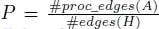 . We can classify different decoder architectures. Partially parallel architectures: Only a subset of edges and nodes are processed in parallel, i.e. P < 1. These architectures are very common for large block sizes that use quasi-cyclic (QC) block codes. An example is the DVB-S2 standard. Fully parallel architectures at iteration level: All edges are processed in parallel, i.e. P = 1. All check nodes and variable nodes are instantiated as hardware units and the corresponding edges are hardwired. Because of the low locality in the Tanner graph, routing congestion (minimizing ω ) is a big challenge in these architectures. Unrolled fully parallel architectures: These architectures are similar to the fully parallel architectures, but, in addition, the iterations are unrolled and pipelined, i.e. P = I . In every clock cycle, a new block is processed. Only this architectural approach is feasible to achieve a throughput towards 1 Tbit/s (Schläfer et al . 2013; Ghanaatian et al . 2018). Figure 2.2 (middle) shows the layout of an (672,420) LDPC decoder using the unrolled fully parallel architecture approach. The decoder is implemented in the same technology and under same PVT assumptions as the Turbo decoder and runs with 400 MHz, achieving a (coded) throughput of 288 Gbit/s. The total area is 3.31 mm 2. Different colors represent the individual iterations (in total 10).
Интервал:
Закладка:
Похожие книги на «Multi-Processor System-on-Chip 2»
Представляем Вашему вниманию похожие книги на «Multi-Processor System-on-Chip 2» списком для выбора. Мы отобрали схожую по названию и смыслу литературу в надежде предоставить читателям больше вариантов отыскать новые, интересные, ещё непрочитанные произведения.


Обсуждение, отзывы о книге «Multi-Processor System-on-Chip 2» и просто собственные мнения читателей. Оставьте ваши комментарии, напишите, что Вы думаете о произведении, его смысле или главных героях. Укажите что конкретно понравилось, а что нет, и почему Вы так считаете.