Substrate-Integrated Millimeter-Wave Antennas for Next-Generation Communication and Radar Systems
Здесь есть возможность читать онлайн «Substrate-Integrated Millimeter-Wave Antennas for Next-Generation Communication and Radar Systems» — ознакомительный отрывок электронной книги совершенно бесплатно, а после прочтения отрывка купить полную версию. В некоторых случаях можно слушать аудио, скачать через торрент в формате fb2 и присутствует краткое содержание. Жанр: unrecognised, на английском языке. Описание произведения, (предисловие) а так же отзывы посетителей доступны на портале библиотеки ЛибКат.
- Название:Substrate-Integrated Millimeter-Wave Antennas for Next-Generation Communication and Radar Systems
- Автор:
- Жанр:
- Год:неизвестен
- ISBN:нет данных
- Рейтинг книги:4 / 5. Голосов: 1
-
Избранное:Добавить в избранное
- Отзывы:
-
Ваша оценка:
Substrate-Integrated Millimeter-Wave Antennas for Next-Generation Communication and Radar Systems: краткое содержание, описание и аннотация
Предлагаем к чтению аннотацию, описание, краткое содержание или предисловие (зависит от того, что написал сам автор книги «Substrate-Integrated Millimeter-Wave Antennas for Next-Generation Communication and Radar Systems»). Если вы не нашли необходимую информацию о книге — напишите в комментариях, мы постараемся отыскать её.
The first and only comprehensive text on substrate-integrated mmW antenna technology, state-of-the-art antenna design, and emerging wireless applications Substrate-Integrated Millimeter-Wave Antennas for Next-Generation Communication and Radar Systems
Substrate-Integrated Millimeter-Wave Antennas for Next-Generation Communication and Radar Systems
Substrate-Integrated Millimeter-Wave Antennas for Next-Generation Communication and Radar Systems — читать онлайн ознакомительный отрывок
Ниже представлен текст книги, разбитый по страницам. Система сохранения места последней прочитанной страницы, позволяет с удобством читать онлайн бесплатно книгу «Substrate-Integrated Millimeter-Wave Antennas for Next-Generation Communication and Radar Systems», без необходимости каждый раз заново искать на чём Вы остановились. Поставьте закладку, и сможете в любой момент перейти на страницу, на которой закончили чтение.
Интервал:
Закладка:
Wireless communications are rapidly progressing toward high data‐rate and ultra‐low latency for the Internet of Things (IoT). Due to the requirement to support higher data‐rate, mmW technology is promising for 5G networks over the frequency range from 24 to 86 GHz. Investment on the research and technology development of mmW cellular mobile networks and WLAN/WiFi infrastructures is increasing exponentially. For instance, mmW technology is the main candidate for the concept of small cells for future cellular network implementation. The mmW technology can be used not only for mobile terminals but also for point‐to‐point backhauls, to some degree to replace traditional fiber optic transmission lines by connecting mobile base stations (BSs).
Table 1.3 Selected key milestones of research and development of mmW technology by 1980s.
| Period | Important activities | Typical applications | Selected references |
|---|---|---|---|
| 1890–1945 | Hertz and Lebedew's experiments in centimeter / millimeter wavelengthNichols, Tear, and Glagolewa‐Arkadiewa developed instruments extended to 0.22 and 0.082 mm using spark‐gap generatorCleeton and William developed vacuum tube sourcesBoot and Randall developed cavity magnetron for radar | Confirmed Maxwell's predictionRadiometermmW sources10 and 24‐GHz radar | [5–10] |
| 1947–1965 | Atmospheric attenuation measurement by Beringer, Van Vleck's and GordyAll circular‐electric mode transmission with all RF components by Bell LabsGeodesic lens antenna by Georgia Technology58‐GHz broad‐brand helix traveling‐wave amplifiers by Bell Labs150‐GHz backward‐wave oscillators by Thomson‐CSF, FranceImaging line, its associated components and surface‐wave propagation on Goubau line or Sommerfeld wave on uncoated metal wire by WiltseFirst IRE Millimeter and Sub‐millimeter Conference held in Orlando, FL, USA in 1963First special issue of The IEEE Proceedings published in April 1966 | Point‐to‐point transmissionThe first 14‐km long transmission systemSpectroscopy70‐GHz radarmmW sourcesHigh‐power mmW sources | [11–17] |
| 1965–1984 | Development of components at 35, 94, 140, and 220‐GHz by US Army Ballistic Research Laboratory as well as Royal Radar Establishment, UKThe first special issue of the IEEE Transaction on Antennas and Propagation about millimeter wave antennas and propagation.Solid state source | RadiometersRadarsMissile guidanceCommunications | More details can be found at [18–20] |
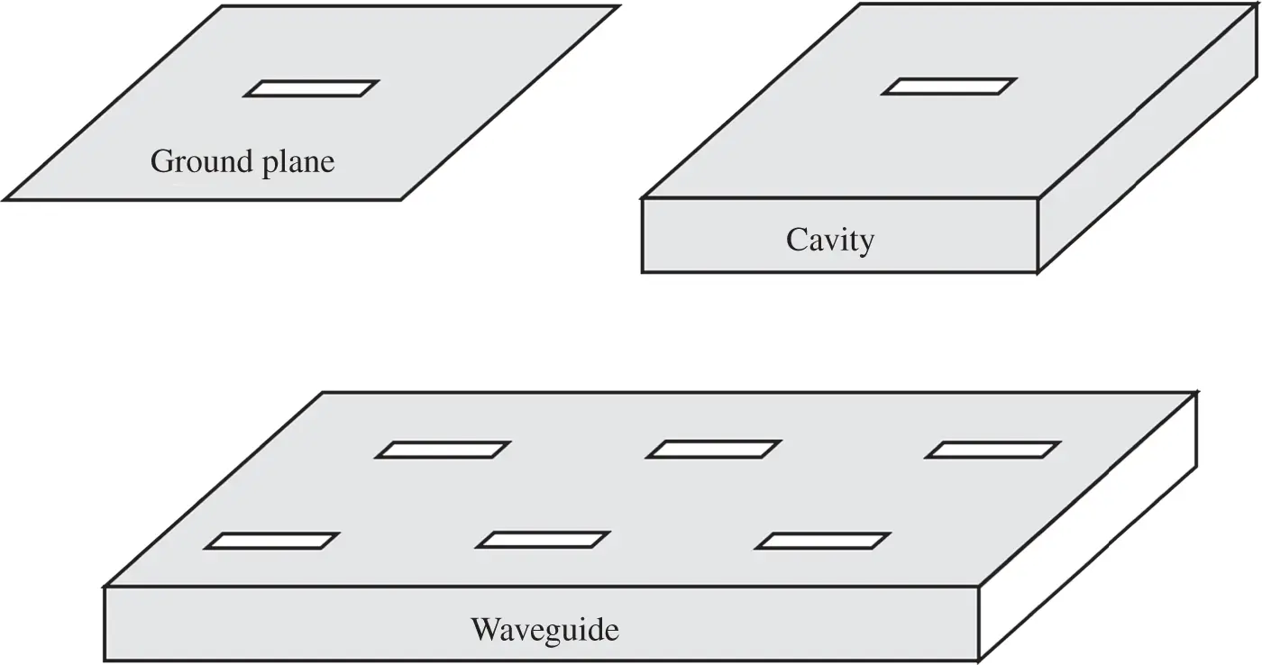
Figure 1.3 Slot antennas.
1.3.2.2 High‐Definition Video and Virtual Reality Headsets
The transmission of 1080p high‐definition (HD) video needs the data‐rate up to gigabits per second. None of the existing wireless microwave links can support such high speed at any sub‐6 GHz bands. The 60‐GHz mmW technology operating, for instance, with unlicensed bandwidths up to 5–7 GHz (for example, US: 57.05–64 GHz and Europe: 57.0–66.0 GHz) can be used to transmit HD video from digital set top boxes, laptops, digital video disc (DVD) players, HD game stations, and other HD video sources to HD television (TV) wirelessly. Furthermore, small transmission devices can be integrated into TV sets invisibly.
Similar to the HD video applications scenarios, virtual reality (VR) applications need ultra‐high data‐rate wireless links in a short range for future multimedia applications. The wireless links will support the high‐speed transmission of video and audio data from mobile devices such as headsets to controlling computers or other VR devices. The mmW wireless communications are the only solution to meet such requirements so far.
1.3.2.3 Automotive Communications and Radars
The mmW radar operating at 24 GHz may be the first mmW system in the history of mmW technology, as shown in Table 1.3. Recently, autonomous driving is being developed very fast. Such applications require the ultra‐high‐resolution detection of pedestrians and other obstructions as well as communication with other vehicles through the network in real time and low latency. Ultra‐high‐resolution radars have been developed with the mmW radar systems operating at a range from 77 to 81 GHz. The detection range varies from 0.15 to 200 m. The communications can be built up to achieve the gigabits per second links through 5G networks.
1.3.2.4 Body Scanners and Imaging
Due to the short wavelength for possible high‐resolution images and high frequency for fast imaging, the mmW technology has been extensively applied in human body scanners currently in the market. The mmW body scanners have achieved high‐precision scanning with much less harm to the human body. In particular, such mmW full‐body scanners have been very popular for airport security. They use the transmitted power of less than 1 mW and operate at a frequency range between 70 and 80 GHz.
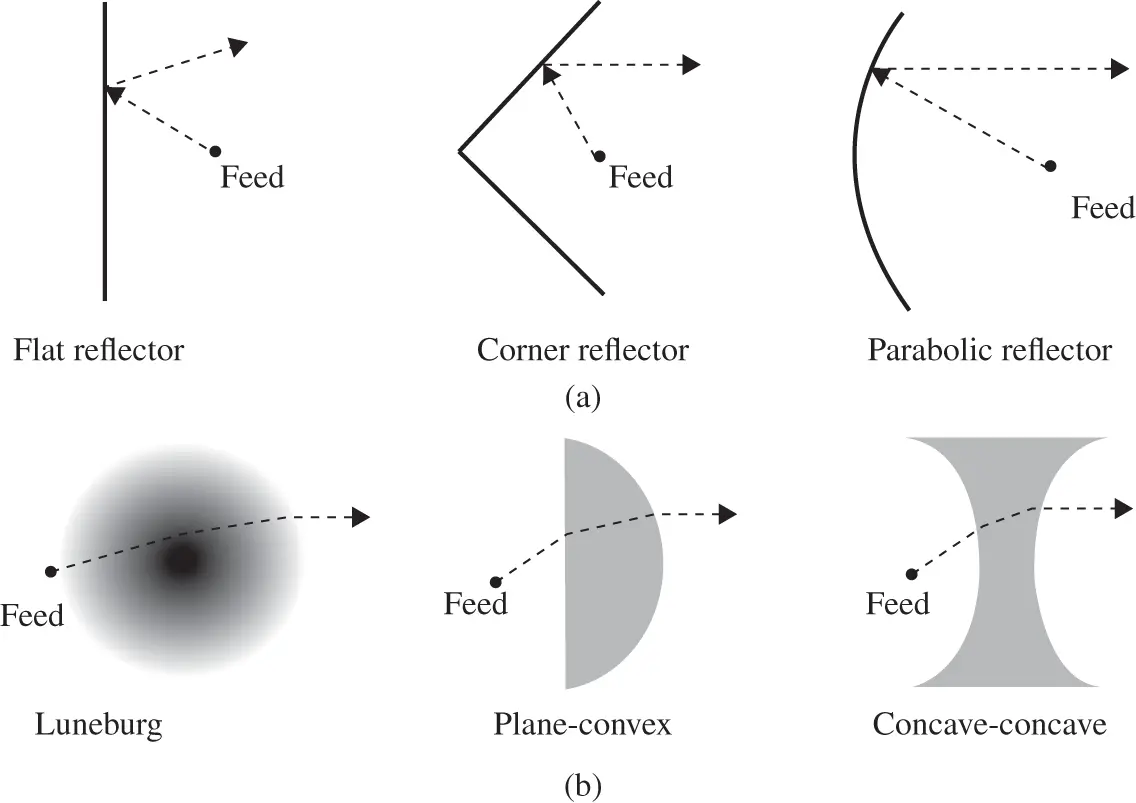
Figure 1.4 (a) Reflector antennas and (b) lens antennas.
In conclusion, with its unique features, the mmW technology has a very promising future in the applications of high‐speed wired/wireless communications as well as radar detection and imaging.
1.4 Unique Challenges of Millimeter Wave Antennas
An antenna is the only means to transfer the electric power from the circuits of a wireless system to a medium and vice versa. There have been many design challenges for conventional antennas such as wide operation bandwidth, high gain and radiation efficiency, desired radiation performance, small/compact size and conformal shapes, and low‐cost material utilization and fabrication. However, the design of antennas for mmW systems faces unique challenges because of its higher frequencies, or shorter wavelengths.
From the design point of view:
1 Wide Bandwidth: At mmW bands, usually we enjoy wide available spectra for wireless communications and radar applications. The typical operating bandwidth is more than 10% for both required impedance matching and desired radiation performance such as radiation patterns, radiation efficiency, and polarization. It is indeed challenging for the antennas to meet all design requirements simultaneously.
2 High Gain: Due to high operating frequencies, the path‐loss in propagation at mmW bands, in particular in rainy, foggy, or snowy weather, becomes much more critical than that at microwave bands. To compensate for the high path‐loss, we must design antennas with much higher gain. For example, the gain of the antennas should reach up to 15 dBi for 10 m LOS wireless links at 60 GHz bands for some systems under the IEEE 802.11ad standard.
3 High Radiation Efficiency: Due to high operating frequencies, the ohmic losses caused by materials and connections in the design become severe. Usually, the loss of the dielectric and metals increase against frequencies. For instance, FR4 has loss tangents of 0.016 at 1 MHz and > 0.1 at 16 GHz, respectively. The other loss can be caused by surface waves due to electrically thick dielectric used in antenna design. For instance, the dielectric substrate of a patch antenna increases its electrical thickness from a typical 0.01 operating wavelength at a frequency of 2.4 GHz to 0.1 wavelength at 24 GHz if the same dielectric substrate is used for the patch antenna design. The thicker substrate inevitably causes severer surface waves. The increased surface waves guide part of the radiated power to other directions rather than the desired direction, for instance, boresight. Such loss lowers the radiation efficiency or gain of the antenna.
Читать дальшеИнтервал:
Закладка:
Похожие книги на «Substrate-Integrated Millimeter-Wave Antennas for Next-Generation Communication and Radar Systems»
Представляем Вашему вниманию похожие книги на «Substrate-Integrated Millimeter-Wave Antennas for Next-Generation Communication and Radar Systems» списком для выбора. Мы отобрали схожую по названию и смыслу литературу в надежде предоставить читателям больше вариантов отыскать новые, интересные, ещё непрочитанные произведения.


Обсуждение, отзывы о книге «Substrate-Integrated Millimeter-Wave Antennas for Next-Generation Communication and Radar Systems» и просто собственные мнения читателей. Оставьте ваши комментарии, напишите, что Вы думаете о произведении, его смысле или главных героях. Укажите что конкретно понравилось, а что нет, и почему Вы так считаете.