Substrate-Integrated Millimeter-Wave Antennas for Next-Generation Communication and Radar Systems
Здесь есть возможность читать онлайн «Substrate-Integrated Millimeter-Wave Antennas for Next-Generation Communication and Radar Systems» — ознакомительный отрывок электронной книги совершенно бесплатно, а после прочтения отрывка купить полную версию. В некоторых случаях можно слушать аудио, скачать через торрент в формате fb2 и присутствует краткое содержание. Жанр: unrecognised, на английском языке. Описание произведения, (предисловие) а так же отзывы посетителей доступны на портале библиотеки ЛибКат.
- Название:Substrate-Integrated Millimeter-Wave Antennas for Next-Generation Communication and Radar Systems
- Автор:
- Жанр:
- Год:неизвестен
- ISBN:нет данных
- Рейтинг книги:4 / 5. Голосов: 1
-
Избранное:Добавить в избранное
- Отзывы:
-
Ваша оценка:
Substrate-Integrated Millimeter-Wave Antennas for Next-Generation Communication and Radar Systems: краткое содержание, описание и аннотация
Предлагаем к чтению аннотацию, описание, краткое содержание или предисловие (зависит от того, что написал сам автор книги «Substrate-Integrated Millimeter-Wave Antennas for Next-Generation Communication and Radar Systems»). Если вы не нашли необходимую информацию о книге — напишите в комментариях, мы постараемся отыскать её.
The first and only comprehensive text on substrate-integrated mmW antenna technology, state-of-the-art antenna design, and emerging wireless applications Substrate-Integrated Millimeter-Wave Antennas for Next-Generation Communication and Radar Systems
Substrate-Integrated Millimeter-Wave Antennas for Next-Generation Communication and Radar Systems
Substrate-Integrated Millimeter-Wave Antennas for Next-Generation Communication and Radar Systems — читать онлайн ознакомительный отрывок
Ниже представлен текст книги, разбитый по страницам. Система сохранения места последней прочитанной страницы, позволяет с удобством читать онлайн бесплатно книгу «Substrate-Integrated Millimeter-Wave Antennas for Next-Generation Communication and Radar Systems», без необходимости каждый раз заново искать на чём Вы остановились. Поставьте закладку, и сможете в любой момент перейти на страницу, на которой закончили чтение.
Интервал:
Закладка:
It should be noted that the selection of the materials and transmission line systems significantly affects the antenna efficiency. The loss analyses of antennas including their feeding structures are strongly suggested to understand the main causes of the losses in order to control the overall loss by properly selecting the materials and the types of transmission systems, as well as optimizing the design configurations [52].
1.7 Note on Losses in Microstrip‐Lines and Substrate Integrated Waveguides
As previously mentioned, to compensate for the path‐loss at higher frequencies, usually very large‐scale antenna arrays are required in mmW systems. In such large‐scale antenna arrays the feeding network inevitably becomes complicated with a labyrinth of feeding network. The long current or power paths in the network are the critical causes for transmission losses. The additional unignorable transmission losses may be the stopper to limit the achievement of high gain of larger‐scale antenna arrays when the insertion loss cancels the increase in the gain by increasing the number of the elements of arrays. For example, if the insertion loss caused by the increase of the power path of the feeding network reaches nearly 3 dB, the antenna array with doubled number of elements will achieve very little gain enhancement. Therefore, it is important to check the transmission line systems in terms of insertion loss before the design of the arrays at mmW bands.
Next, the insertion losses in microstrip‐lines (MSLs) and SIWs in LTCC at 60 GHz are compared as an example. The LTCC is Ferro A6‐M with relative dielectric constant ε r= 5.9 ± 0.20, loss tangent tanδ = 0.002 at 100 GHz. The conductor used for metallization and vias is Au, whose conductivity is 4.56 × 10 7S·m −1.
Figure 1.6shows a 10‐mm long bent MS transmission line on an LTCC board. The 50‐Ω MSL is with two ports in the simulation. Figure 1.7compares the insertion losses for varying thickness of the LTCC board over a frequency range of 0–70 GHz. It is seen that when the thickness increases, the insertion at higher frequency edge quickly increases. For instance, the loss per centimeter reaches up to 13 dB when the thickness is larger than 0.7 mm.
Figure 1.8clearly shows the causes of the insertion losses at higher frequencies or mmW bands. The losses caused by the dielectric substrate and conductor in the system are just a small percentage of the total losses. It is believed that at 60 GHz, the higher‐order modes excited by the discontinuity of the MS cause large surface wave (SW)/leaky losses as previously discussed. This issue is even severer for the thicker substrate. So the SW of MS at mmW is definitely a big problem for practical antenna design.
Figure 1.9shows a 10‐mm long bent SIW in an LTCC board. Figure 1.10shows the main losses at 60 GHz of a bent SIW in an LTCC board with varying thickness. It is clear that on the contrary, the SIW system does not suffer from such a dilemma, with the highest loss less than 1 dB per centimeter at smaller thicknesses and total losses lower than 0.6 dB for a thickness larger than 0.3 mm. The low‐loss feature is quite stable for all the thicknesses. But actually for the very thin thickness of 0.1 mm, the conductor loss is high for the SIW. Fortunately, the thickness of 0.5 mm is usually selected for SIW at 60 GHz. In particular, the majority of losses are caused by both the dielectric and conductors, which is different from the MS lines.
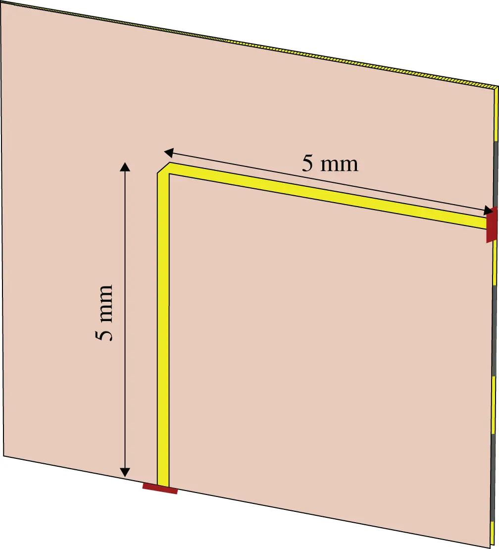
Figure 1.6 A bent MS transmission‐line on a LTCC board.
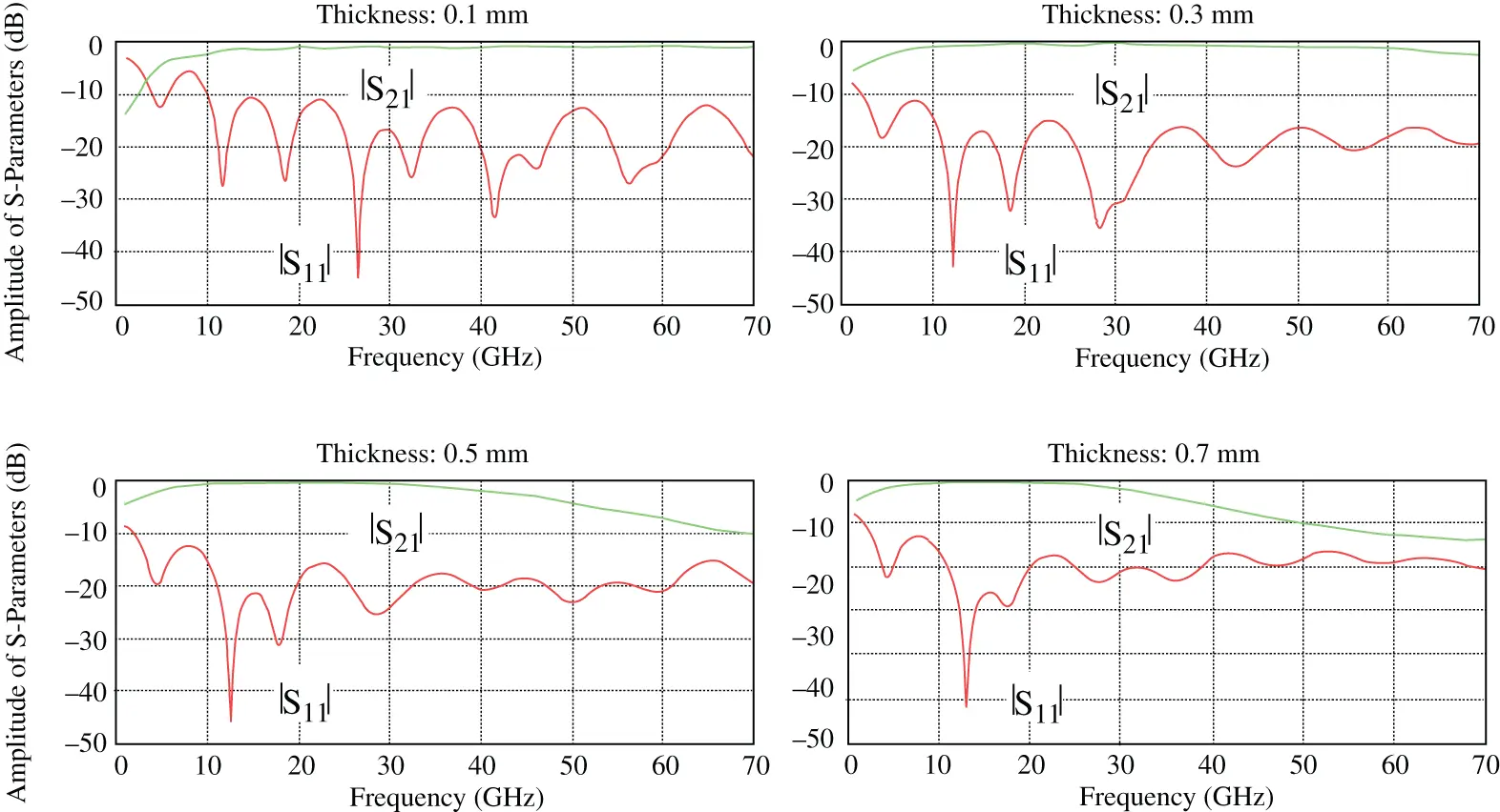
Figure 1.7 The comparison of |S 11| and |S 21| of a bent MS transmission‐line on a LTCC board.
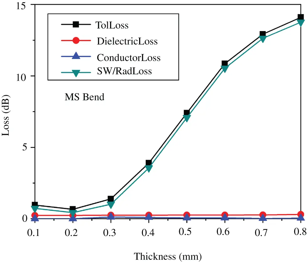
Figure 1.8 The main losses at 60 GHz of a bent MS transmission‐line on a LTCC board with varying thickness.
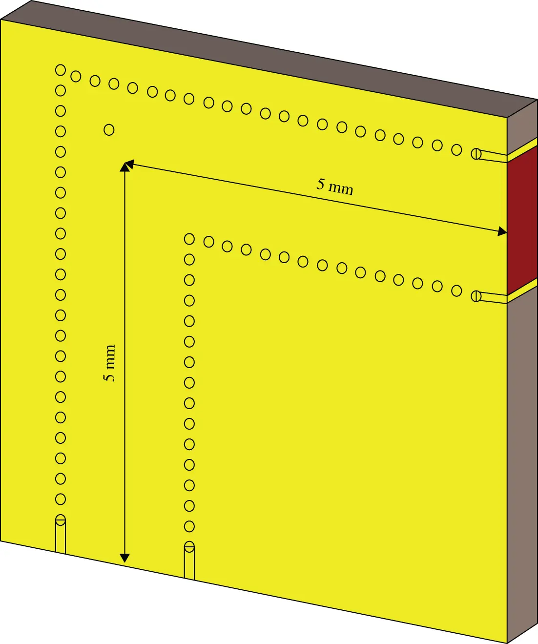
Figure 1.9 A 10‐mm long bent SIW in a LTCC board.
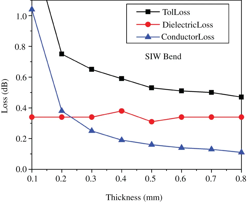
Figure 1.10 The main losses at 60 GHz of a bent SIW in a LTCC board with varying thickness.
In short, the SIW transmission line systems feature lower insertion loss at 60 GHz and above compared with the MS‐lines suffering from several surface wave losses. However, it should be mentioned that the SIW has a more complicated fabrication and higher fabrication cost compared with the MS lines. The evaluation of performance and implementation cost is necessary to make a trade‐off in the design.
1.8 Update of Millimeter Wave Technology in 5G NR and Beyond
Recently mmW has attracted much attention of the industry although it is not a new technology. In particular, the mobile communication networks are significantly increasing their capacity by increasing the usage efficiency of existing spectra such as massive multiple‐input‐multiple‐output (massive MIMO), the number of small cell base stations, and the operating bandwidth by extending operating frequencies from sub‐6 GHz bands to mmW bands to enhance the peak data rates of mobile broadband use case up to 20 Gbps in the downlink (DL) and 10 Gbps in the uplink (UL). With such high data rates, many new applications such as high‐speed streaming of 4K or 8K UHD movies and self‐driving cars will be supported.
According to the release of specifications by The 3rd Generation Partnership Project (3GPP), a standards organization developing the protocols for mobile telephony, the following bands as tabulated in Table 1.5[53] have been defined for fifth‐generation (5G) new radio (NR) networks. The allocated bandwidths reach up to 3 GHz each while the total frequency ranges from 24.25 to 40.00 GHz.
Table 1.6compares the features of mobile communication network operating at 5G NR sub‐6 GHz and mmW bands. Not surprisingly, the systems operating at mmW bands suffer from the higher path‐loss and blocking due to weaker refraction and reflection in propagation in denser environments.
Based on the previous analysis and initial feedback from field trials, the mmW in 5G NR networks will have the typical applications as shown in Figure 1.11. It is estimated that for 5G NR the mmW systems can be used with the similar scenarios at sub‐6 GHz bands, but coverage will be significantly reduced due to the higher path‐loss and blocking of mmW propagation. The higher path‐loss is caused by the reduced physical aperture of receive antennas with the same gain as the antennas operating at lower frequencies. Therefore, the electrical apertures or gain of the mmW antennas should be increased to keep the gain unchanged or link budget compared with the antennas operating at lower frequencies.
Table 1.5 mmW frequency ranges for 5G NR (TDD).
| NR operating band | F UL/DL_low– F UL/DL_high |
|---|---|
| n257 | 26.50–29.50 GHz |
| n258 | 24.25–27.50 GHz |
| n260 | 37.00–40.00 GHz |
Duplex Mode: Time‐division duplexing (TDD)
Читать дальшеИнтервал:
Закладка:
Похожие книги на «Substrate-Integrated Millimeter-Wave Antennas for Next-Generation Communication and Radar Systems»
Представляем Вашему вниманию похожие книги на «Substrate-Integrated Millimeter-Wave Antennas for Next-Generation Communication and Radar Systems» списком для выбора. Мы отобрали схожую по названию и смыслу литературу в надежде предоставить читателям больше вариантов отыскать новые, интересные, ещё непрочитанные произведения.


Обсуждение, отзывы о книге «Substrate-Integrated Millimeter-Wave Antennas for Next-Generation Communication and Radar Systems» и просто собственные мнения читателей. Оставьте ваши комментарии, напишите, что Вы думаете о произведении, его смысле или главных героях. Укажите что конкретно понравилось, а что нет, и почему Вы так считаете.