Substrate-Integrated Millimeter-Wave Antennas for Next-Generation Communication and Radar Systems
Здесь есть возможность читать онлайн «Substrate-Integrated Millimeter-Wave Antennas for Next-Generation Communication and Radar Systems» — ознакомительный отрывок электронной книги совершенно бесплатно, а после прочтения отрывка купить полную версию. В некоторых случаях можно слушать аудио, скачать через торрент в формате fb2 и присутствует краткое содержание. Жанр: unrecognised, на английском языке. Описание произведения, (предисловие) а так же отзывы посетителей доступны на портале библиотеки ЛибКат.
- Название:Substrate-Integrated Millimeter-Wave Antennas for Next-Generation Communication and Radar Systems
- Автор:
- Жанр:
- Год:неизвестен
- ISBN:нет данных
- Рейтинг книги:4 / 5. Голосов: 1
-
Избранное:Добавить в избранное
- Отзывы:
-
Ваша оценка:
Substrate-Integrated Millimeter-Wave Antennas for Next-Generation Communication and Radar Systems: краткое содержание, описание и аннотация
Предлагаем к чтению аннотацию, описание, краткое содержание или предисловие (зависит от того, что написал сам автор книги «Substrate-Integrated Millimeter-Wave Antennas for Next-Generation Communication and Radar Systems»). Если вы не нашли необходимую информацию о книге — напишите в комментариях, мы постараемся отыскать её.
The first and only comprehensive text on substrate-integrated mmW antenna technology, state-of-the-art antenna design, and emerging wireless applications Substrate-Integrated Millimeter-Wave Antennas for Next-Generation Communication and Radar Systems
Substrate-Integrated Millimeter-Wave Antennas for Next-Generation Communication and Radar Systems
Substrate-Integrated Millimeter-Wave Antennas for Next-Generation Communication and Radar Systems — читать онлайн ознакомительный отрывок
Ниже представлен текст книги, разбитый по страницам. Система сохранения места последней прочитанной страницы, позволяет с удобством читать онлайн бесплатно книгу «Substrate-Integrated Millimeter-Wave Antennas for Next-Generation Communication and Radar Systems», без необходимости каждый раз заново искать на чём Вы остановились. Поставьте закладку, и сможете в любой момент перейти на страницу, на которой закончили чтение.
Интервал:
Закладка:
At the mmW bands, multilayered substrates such as polytetrafluoroethylene (PTFE), a synthetic fluoropolymer of tetrafluoroethylene, and PTFE composite filled with random glass or ceramic such as RT/duroid® are commonly used for laminating circuits and antennas. PTFE‐based substrates usually feature a low and stable loss tangent typically of 0.0018 at 10 GHz and even higher and high resistance to chemical processing and are waterproof and thermally stable. PTFE‐based substrates, however, suffer from a higher cost compared to FR4 glass epoxy, are softer materials, and have a higher thermal expansion coefficient. FR4 glass epoxy is most commonly used in frequencies lower than 3 GHz because of its increasing loss tangent against frequency.
LCPs are a class of aromatic polymers. The unique feature of the LCP substrate is its softness although it has similar properties to PTFE‐based substrates such as extreme chemical resistance, high mechanical strength at high temperatures, and inertness. Its poor thermal conductivity and surface roughness should be taken into account in electrical applications, in particular, at mmW bands.
To meet the requirements of fabrication tolerance, electrical, and other mechanical properties, low temperature co‐fired ceramic (LTCC) has long been used as a cost‐effective substrate technology in electrical and electronic engineering, especially at higher frequencies. LTCC is a multilayered glass ceramic substrate. It is co‐fired with low‐resistance metal conductors, such as Au or Ag, at low firing temperatures, usually ∼850–900 °C, compared with high temperature multilayered ceramic sintered at ∼1600–1800 °C. There have been many ceramic materials developed by commercial companies. More detailed information can be found in the book [28], which studies a variety of electrical materials for mmW applications. In particular, the information about the ceramic materials used in LTCC is comprehensive.
For example, Ferro A6M has been widely used in applications at mmW bands. It has a relative dielectric constant of 5.9–6.5 and loss tangent of ∼0.001–0.005 at 3 GHz. In particular, the electrical properties are stable against frequency. The relative dielectric constant and loss tangent of DuPont 951 ceramic are ∼7.85 and 0.0063 at 3 GHz, respectively. It should be noted that the ceramic used in LTCC usually has the relative dielectric constants of ∼6–10, sometimes ∼18 [29]. High relative dielectric constants are usually not desired for antenna design at mmW bands because they will shrink the dimensions of antennas so that the fabrication needs much higher accuracy [30].
With an LTCC process, the LTCC ceramic substrate can host almost an infinite number of layers. The thin layers are stacked one on the top of another. The conducting paths of gold or silver thick film pastes are printed on each surface layer by layer using the silk‐screen printing method. When the multilayer setup has been stacked and printed, it is then fired in the process oven where the low sintering temperature allows the use of gold and silver as conducting traces. The simplified description of process includes:
Step I: via punch, via conductor fill, and trace printing;
Step II: layer stack and lamination; and
Step III: layer co‐fire.
The PCB and LTCC processes are concisely compared in Figure 1.5. From a waveguide feeding network and antenna design point of view, the most important difference between the PCB and LTCC processes is that the LTCC process is able to implement the blind via and embedded cavity while the PCB process is unable to do it.
Furthermore, the LTCC used for SIA designs also increases the advantages such as low loss tangents, low permittivity tolerance, good thermal conductivity, multilayered substrate, cavities/embedded cavities, low material costs for silver or gold conductor paths, easy integration with other circuits, and low production costs for medium and large quantities.
In our experience, the PCB process is preferred for SIA designs when an operating frequency is lower than 60 GHz, while LTCC is a good candidate antennas operating at frequencies higher than 60 GHz and up to 300 GHz. At frequencies higher than 300 GHz, the LTCC fabrication becomes quite challenging because of its process limit such as via‐hole pitch.
1.6.2 Commonly Used Transmission Line Systems for Antennas
Like any antenna systems, their feeding structures will be a critical issue in the implementation of the antenna design. In particular, the losses caused in the feeding networks greatly degrade the performance of the antenna arrays at mmW bands. Unlike the antennas at microwave bands, the losses can be caused by not only the dielectric substrate but also metals used as conductors for transmission and radiation. Like any dielectric at microwave bands, the loss of a dielectric substrate is measured by its loss tangent. Different from the designs at microwave bands, the metal loss that may be caused by the conductivity and surface roughness of the conductors can't be ignored.
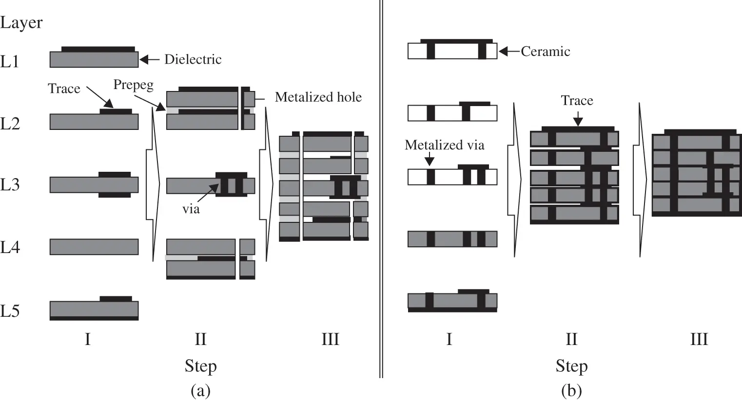
Figure 1.5 Simplified descriptions of PCB and LTCC processes. (a) PCB and (b) LTCC.
Besides microstrip transmission lines, the waveguide‐type transmission line systems are popularly used because they may enjoy the lower losses caused by dielectric and metals at mmW bands [23–27, 31]. Accordingly, for instance, the loss analyses have been conducted for microstrip lines, solid‐metal‐wall waveguides, and post‐wall or laminated waveguide or SIW [32]. The study shows that in general the solid‐metal‐wall waveguides without dielectric loss enjoy less metal loss while microstrip lines suffer from several dielectric losses. The post‐wall waveguides or SIWs feature acceptable total losses caused by both dielectric and metal losses at mmW bands. However, it should be noted that the causes of losses of transmission line systems can be complicated because they will be determined by the materials such as dielectric and metals as well as the types or configurations of transmission lines.
The transmission line systems can be in the form of microstrip lines and coaxial lines. Compared with conventional cylindrical versions, the substrate integrated coaxial line (SICL) is a type of planar rectangular coaxial lines. The lines comprise a strip sandwiched between two grounded dielectric layers and laterally shielded by the arrays of metallized vias [33]. Similar to the conventional coaxial line, the propagation of SICL is still in the dominant mode of transverse electromagnetic (TEM).
The SICLs can be realized using a traditional multilayer PCB or LTCC process. Therefore, SICLs feature the combined advantages of the coaxial lines and the planar transmission lines, including the wideband unimodal operation, low cost, non‐dispersive performance, good electromagnetic compatibility, and easy integration with other planar circuits. It has been used for high‐speed data transmission [34] and various other applications such as antennas, couplers, baluns, and filters at mmW bands [35–41].
Moreover, the substrate integrated gap waveguide (SIGW) or printed ridge gap waveguide (PRGW) is proposed for the transmission line systems at mmW bands. The SIGW or PRGW is the combination of the microstrip‐line and gap‐waveguide technology based on the PCB or LTCC process [42–44]. The invertedprinted strip line is arranged on or above the periodic mushroom structures where the unwanted surface waves are suppressed and only the quasi‐TEM mode is permitted over the operating band. Unlike SIW or SICL, the top and bottom grounds of a SIGW are unconnected. Therefore, the processing complexity is greatly reduced. The SIGW/PRGW technology has been widely used in the antennas and arrays at mmW bands [44–51].
Читать дальшеИнтервал:
Закладка:
Похожие книги на «Substrate-Integrated Millimeter-Wave Antennas for Next-Generation Communication and Radar Systems»
Представляем Вашему вниманию похожие книги на «Substrate-Integrated Millimeter-Wave Antennas for Next-Generation Communication and Radar Systems» списком для выбора. Мы отобрали схожую по названию и смыслу литературу в надежде предоставить читателям больше вариантов отыскать новые, интересные, ещё непрочитанные произведения.


Обсуждение, отзывы о книге «Substrate-Integrated Millimeter-Wave Antennas for Next-Generation Communication and Radar Systems» и просто собственные мнения читателей. Оставьте ваши комментарии, напишите, что Вы думаете о произведении, его смысле или главных героях. Укажите что конкретно понравилось, а что нет, и почему Вы так считаете.