Anand K. Verma - Introduction To Modern Planar Transmission Lines
Здесь есть возможность читать онлайн «Anand K. Verma - Introduction To Modern Planar Transmission Lines» — ознакомительный отрывок электронной книги совершенно бесплатно, а после прочтения отрывка купить полную версию. В некоторых случаях можно слушать аудио, скачать через торрент в формате fb2 и присутствует краткое содержание. Жанр: unrecognised, на английском языке. Описание произведения, (предисловие) а так же отзывы посетителей доступны на портале библиотеки ЛибКат.

- Название:Introduction To Modern Planar Transmission Lines
- Автор:
- Жанр:
- Год:неизвестен
- ISBN:нет данных
- Рейтинг книги:4 / 5. Голосов: 1
-
Избранное:Добавить в избранное
- Отзывы:
-
Ваша оценка:
Introduction To Modern Planar Transmission Lines: краткое содержание, описание и аннотация
Предлагаем к чтению аннотацию, описание, краткое содержание или предисловие (зависит от того, что написал сам автор книги «Introduction To Modern Planar Transmission Lines»). Если вы не нашли необходимую информацию о книге — напишите в комментариях, мы постараемся отыскать её.
rovides a comprehensive discussion of planar transmission lines and their applications, focusing on physical understanding, analytical approach, and circuit models
Planar transmission lines form the core of the modern high-frequency communication, computer, and other related technology. This advanced text gives a complete overview of the technology and acts as a comprehensive tool for radio frequency (RF) engineers that reflects a linear discussion of the subject from fundamentals to more complex arguments.
Introduction to Modern Planar Transmission Lines: Physical, Analytical, and Circuit Models Approach Emphasizes modeling using physical concepts, circuit-models, closed-form expressions, and full derivation of a large number of expressions Explains advanced mathematical treatment, such as the variation method, conformal mapping method, and SDA Connects each section of the text with forward and backward cross-referencing to aid in personalized self-study
is an ideal book for senior undergraduate and graduate students of the subject. It will also appeal to new researchers with the inter-disciplinary background, as well as to engineers and professionals in industries utilizing RF/microwave technologies.
Introduction To Modern Planar Transmission Lines — читать онлайн ознакомительный отрывок
Ниже представлен текст книги, разбитый по страницам. Система сохранения места последней прочитанной страницы, позволяет с удобством читать онлайн бесплатно книгу «Introduction To Modern Planar Transmission Lines», без необходимости каждый раз заново искать на чём Вы остановились. Поставьте закладку, и сможете в любой момент перейти на страницу, на которой закончили чтение.
Интервал:
Закладка:
Figure (5.16b)also shows the equivalent transmission line model. The total surface impedance that creates a metasurface is
(5.5.44) 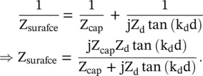
where Z dand k dare characteristic impedance and wavevector of the conductor backed dielectric sheet. At a certain resonance frequency, the denominator of the above expression is zero giving the needed value of the surface impedance Z capof the capacitive grid:
(5.5.45) 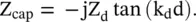
The surface parallel resonance creates the high impedance metasurface at which the resistive screen is located. In this case, Z surafce(ω res) = R s(Screen) = 377 Ω is obtained to achieve matching condition. The absorbed RF power is dissipated in the resistive screen to get nearly perfect absorber. By using multilayer metasurface, the broadband thin absorber has been developed.
DNG Slab Absorber
The lossy DNG slab can also be used as a perfect absorber, in place of the metasurface and resistive screen combination. The DNG slab absorber is developed around two configurations shown in Fig (5.17). Figure (5.17a)shows the lossy DNG slab with a conductor backing, and Fig (5.17b)shows it without any conductor backing. The working principle of a lossy DNG slab absorber is completely different. However, it is not based on the negative refraction property and backward wave nature of the DNG medium.
The characteristic impedance of any magneto‐dielectric slab, DPS or DNG, is computed as 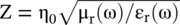 . The impedance matching with free space could be achieved μ r(ω) = ε r(ω). Such natural DPS materials are not available. However, μ r(ω) and ε r(ω) of a DNG slab are engineered using two different structures. So both μ r(ω) and ε r(ω) can be tuned independently to obtain their equalization at the same frequency. Thus, impedance matching could be realized in a DNG slab. If a DNG slab is sufficiently lossy, then absorbed RF power could be dissipated in the DNG slab of appropriate thickness.
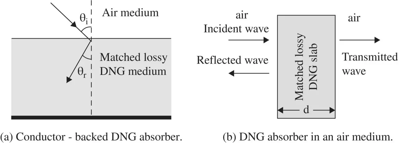
Figure 5.17 Free space matched lossy DNG absorber.
Lossy DNG Slab with Conductor Backing
Figure (5.17a)shows the obliquely incident wave on a conductor backed lossy DNG slab. The angle of refraction is negative. The incident wave could be either TE or TM‐polarized discussed in section ( 5.2). Following the results of equations (5.2.8c)and (5.2.16c)the reflection coefficients of both polarizations could be written as follows:
(5.5.46) 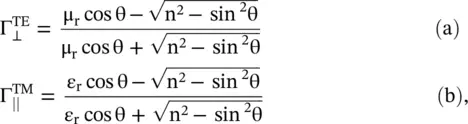
where θ i= θ is the angle of incidence,  is the refractive index of a DNG slab and (μ r, ε r) are material parameters of the DNG medium. The reflectivity
  for the incident TE and TM‐polarized waves is defined as
 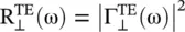 and
and 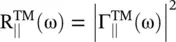 . In the case of normal incidence θ = 0 ∘, the above results provide the following expression for reflectivity:
(5.5.47) 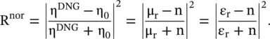
To get no reflection, i.e. for R nor= 0, the material parameters are n = ε r, i. e. μ r= ε r. Thus, the DNG slab is impedance matched i.e. 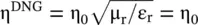 . The transmission coefficient τ norand transmissivity T norof a normally incident wave on the impedance matched DNG slab is obtained from equation (5.4.15):
(5.5.48) 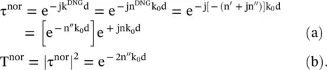
The condition 2n ″k 0d min= 1 provides the minimum propagation depth to attenuate the absorbed RF power to 1/e:
(5.5.49) 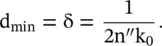
The conductor backing reflects the attenuated EM‐wave that gets further attenuated by 1/e before appearing as the reflected wave from the air‐DNG interface. It degrades the absorption of the absorbing slab. An expression for the reflection coefficient is available, using the theory of multiple reflections [J.29]. However, for a thicker slab, multiple reflections can be ignored and simpler expression can be used to get the absorptivity of an absorber:
(5.5.50) 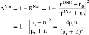
Lossy DNG Slab Without Conductor Backing
Figure (5.17b)shows the matched DNG slab without any conductor backing. In this case, the impedance matching of the DNG slab is also obtained for the condition μ r= ε r. The transmissivity of a normally incident wave is given by equation (5.5.48b). A thicker DNG slab is taken (d >> d min) to reduce the transmissivity T almost to a negligible value.
Both arrangements can be simulated using the Drude–Lorentz model discussed in chapter 6. We have discussed only the case of a single‐layered DNG absorber. It has a limited bandwidth, as μ r= ε ris obtained at one frequency. However, several thin layers of the lossy DNG could be stacked to get a wideband absorber. The multiple resonance DNG slabs provide multiband absorber also [J.32–J.35].
The metamaterials have several other characteristics and applications. For instance, the DNG medium could be tailored to hide an object from the incident waves. It leads to the concept of cloaking . The cloak to hide any object is designed using the concept of the transformation electromagnetics [J.36]. The graded anisotropic refractive index between zero and unity is obtained through transformation electromagnetics. The metamaterials are used from microwave to optical frequency ranges, including the THz band [B.16]. Chapter 21discusses realization and some applications of metamaterial in planar technology.
Читать дальшеИнтервал:
Закладка:
Похожие книги на «Introduction To Modern Planar Transmission Lines»
Представляем Вашему вниманию похожие книги на «Introduction To Modern Planar Transmission Lines» списком для выбора. Мы отобрали схожую по названию и смыслу литературу в надежде предоставить читателям больше вариантов отыскать новые, интересные, ещё непрочитанные произведения.


Обсуждение, отзывы о книге «Introduction To Modern Planar Transmission Lines» и просто собственные мнения читателей. Оставьте ваши комментарии, напишите, что Вы думаете о произведении, его смысле или главных героях. Укажите что конкретно понравилось, а что нет, и почему Вы так считаете.