Anand K. Verma - Introduction To Modern Planar Transmission Lines
Здесь есть возможность читать онлайн «Anand K. Verma - Introduction To Modern Planar Transmission Lines» — ознакомительный отрывок электронной книги совершенно бесплатно, а после прочтения отрывка купить полную версию. В некоторых случаях можно слушать аудио, скачать через торрент в формате fb2 и присутствует краткое содержание. Жанр: unrecognised, на английском языке. Описание произведения, (предисловие) а так же отзывы посетителей доступны на портале библиотеки ЛибКат.

- Название:Introduction To Modern Planar Transmission Lines
- Автор:
- Жанр:
- Год:неизвестен
- ISBN:нет данных
- Рейтинг книги:4 / 5. Голосов: 1
-
Избранное:Добавить в избранное
- Отзывы:
-
Ваша оценка:
Introduction To Modern Planar Transmission Lines: краткое содержание, описание и аннотация
Предлагаем к чтению аннотацию, описание, краткое содержание или предисловие (зависит от того, что написал сам автор книги «Introduction To Modern Planar Transmission Lines»). Если вы не нашли необходимую информацию о книге — напишите в комментариях, мы постараемся отыскать её.
rovides a comprehensive discussion of planar transmission lines and their applications, focusing on physical understanding, analytical approach, and circuit models
Planar transmission lines form the core of the modern high-frequency communication, computer, and other related technology. This advanced text gives a complete overview of the technology and acts as a comprehensive tool for radio frequency (RF) engineers that reflects a linear discussion of the subject from fundamentals to more complex arguments.
Introduction to Modern Planar Transmission Lines: Physical, Analytical, and Circuit Models Approach Emphasizes modeling using physical concepts, circuit-models, closed-form expressions, and full derivation of a large number of expressions Explains advanced mathematical treatment, such as the variation method, conformal mapping method, and SDA Connects each section of the text with forward and backward cross-referencing to aid in personalized self-study
is an ideal book for senior undergraduate and graduate students of the subject. It will also appeal to new researchers with the inter-disciplinary background, as well as to engineers and professionals in industries utilizing RF/microwave technologies.
Introduction To Modern Planar Transmission Lines — читать онлайн ознакомительный отрывок
Ниже представлен текст книги, разбитый по страницам. Система сохранения места последней прочитанной страницы, позволяет с удобством читать онлайн бесплатно книгу «Introduction To Modern Planar Transmission Lines», без необходимости каждый раз заново искать на чём Вы остановились. Поставьте закладку, и сможете в любой момент перейти на страницу, на которой закончили чтение.
Интервал:
Закладка:
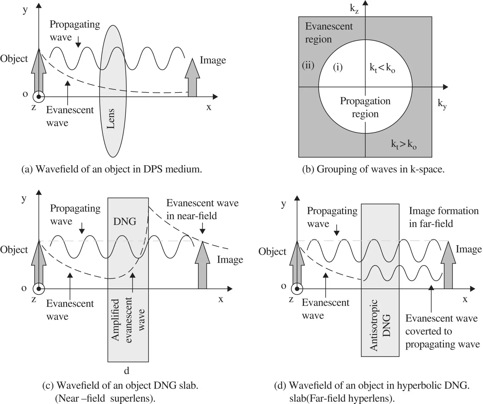
Figure 5.12 Creation of image using wave optics.
(5.5.27) 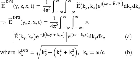
The wave propagates in the x‐direction and the spectral field components are in the (k y− k z)‐plane. The spectral field amplitudes  with phase distribution within the bracket [ ] are Fourier components of the electric field
  . The propagation constant
  of the plane wave, given by equation (5.5.27b), is obtained from the dispersion relation ( 4.5.29d) of chapter 4. The propagation constant
  of propagating plane waves must be a real quantity, whereas imaginary values of
  provide decaying evanescent waves in the x‐direction. Thus, Fourier components of the wave originated by an object could be divided into two groups: propagating waves and nonpropagating evanescent waves . The grouping of waves is shown in Fig (5.12b). In a DPS medium, the propagation constants for both groups of waves, from equation (5.5.27b), could be written as follows:
(5.5.28) 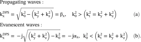
The electric fields of both the propagating and evanescent waves in the DPS medium could be written from the above relations as follows:
(5.5.29) 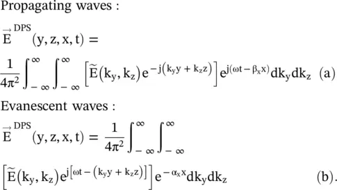
Figure (5.12a)shows both the propagating and exponentially decaying evanescent waves in the DPS medium, generated by an object. The evanescent waves decay fast within a distance under λ. The higher value of transverse components of the wavevector (k y, k z) corresponds to the finer spatial details of the object. So at the image-plane, finer spatial details of an image are lost. The DPS based lens cannot recover the lost spatial details in the evanescent waves. The maximum value of the transverse wavevector 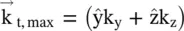 at the cut‐off wavenumber k x= 0 determines the limit of the finer spatial details, i.e. the diffraction limit:
(5.5.30) 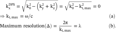
The maximum resolution Δ is the minimum adjacent distance of the finer spatial details of the object. It called the diffraction limit . The relation Δ × k t,max= 2π is obtained in subsection (19.1.1) of chapter 19from the relation between the direct space period (Δ) and the propagation vector in the k‐space. The diffraction limit for a very wide lens aperture could be reduced to λ/2 [J.13].
The DNG planar slab acts as a flat lens [J.2, J.13–J.15, J.22]. The DNG slab provides exponentially increasing evanescent waves inside the slab. So the DNG can compensate for the decaying evanescent waves that reach the image plane creating a high‐resolution image with finer details. It is shown in Fig (5.12c). It is also examined in the next sub section (5.5.6).
5.5.6 DNG Flat Lens and Superlens
The focal length (f) of a thin lens is related to its radius of curvature (R) by the expression f = R/(n − 1), where n is the refractive index of a lens. For n = +1, the lens does not refract, and the focusing of the EM‐wave at the image plane does not occur. However, for a DNG lens with n = −1, refraction occurs. Veselago [J.3] has shown that due to negative refraction in a DNG slab, even a slab acts as a flat lens . Pendry has further shown that such a lens is a perfect lens in the near‐field region as it enables recovery of the decaying evanescent field at the image plane [J.2]. Such recovery of the evanescent waves is not possible with a normal lens, irrespective of the size of its aperture. The perfect lens, also called the superlens , has a subwavelength resolution, breaking the diffraction limit barrier. The superlens creates an image in the near‐field very close to the lens, so it is difficult to use it in practice. However, anisotropic hyperbolic DNG lens creates a perfect image in the far‐field region , by converting the evanescent waves into the propagating waves. Such a lens is called the hyperlens . The proof of concept has been demonstrated experimentally for both the superlens and hyperlens in optical and microwave range. The proper functioning of these lenses is limited by the losses associated with a DNG medium. A brief theory of three lenses is presented in this section.
Veselago Flat Lens
Figure (5.13)shows the ray diagram of a DNG slab acting as a lens due to the negative refraction [J.3]. It has two foci N and Q. The focal length f 1of focus N is located inside the DNG slab of thickness d. The focal length f 2of focus Q is located outside the slab. To avoid mismatch at the interface, the DNG slab has μ r= ε r= − 1 and  . Figure (5.13)shows the angles of incidence θ iand refraction θ rand other geometrical dimensions. Snell's law for the DNG slab is written below:
(5.5.31) 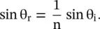
The first focal length f 1is determined as follows:
(5.5.32) 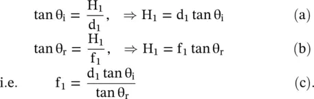
The incident ray OM and the output ray P 1Q are parallel, i.e. θ i= θ o.
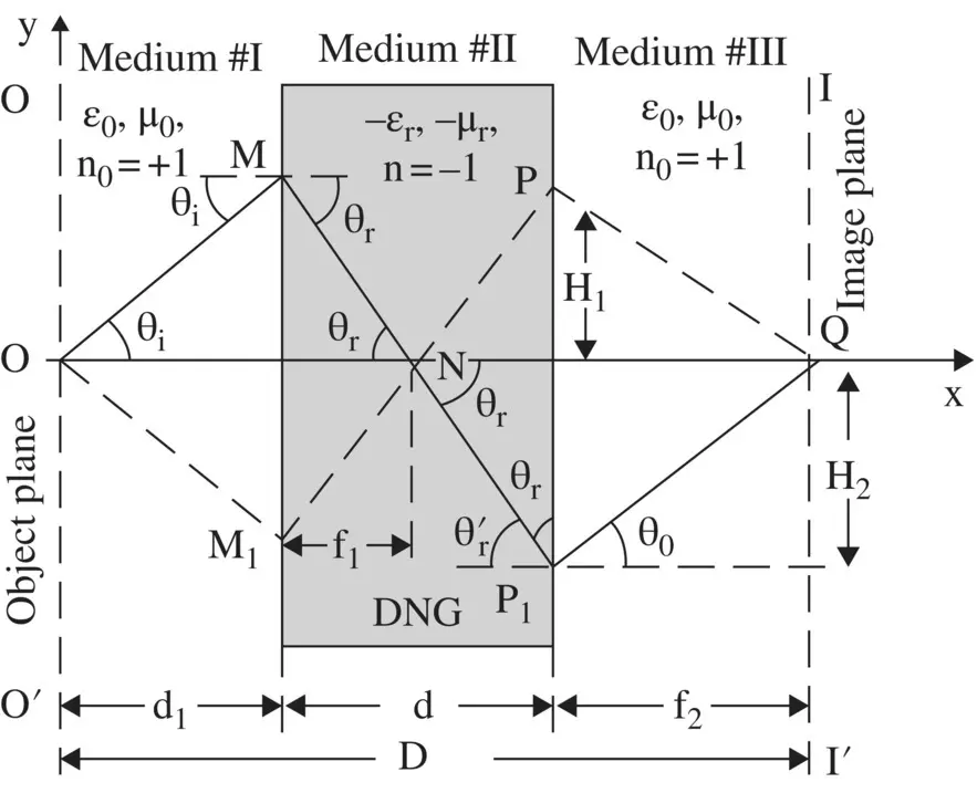
Figure 5.13 Ray diagram of a DNG flat lens.
The second focal length f 2is computed as follows:
(5.5.33) 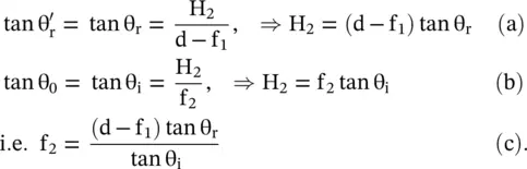
Интервал:
Закладка:
Похожие книги на «Introduction To Modern Planar Transmission Lines»
Представляем Вашему вниманию похожие книги на «Introduction To Modern Planar Transmission Lines» списком для выбора. Мы отобрали схожую по названию и смыслу литературу в надежде предоставить читателям больше вариантов отыскать новые, интересные, ещё непрочитанные произведения.


Обсуждение, отзывы о книге «Introduction To Modern Planar Transmission Lines» и просто собственные мнения читателей. Оставьте ваши комментарии, напишите, что Вы думаете о произведении, его смысле или главных героях. Укажите что конкретно понравилось, а что нет, и почему Вы так считаете.