Anand K. Verma - Introduction To Modern Planar Transmission Lines
Здесь есть возможность читать онлайн «Anand K. Verma - Introduction To Modern Planar Transmission Lines» — ознакомительный отрывок электронной книги совершенно бесплатно, а после прочтения отрывка купить полную версию. В некоторых случаях можно слушать аудио, скачать через торрент в формате fb2 и присутствует краткое содержание. Жанр: unrecognised, на английском языке. Описание произведения, (предисловие) а так же отзывы посетителей доступны на портале библиотеки ЛибКат.

- Название:Introduction To Modern Planar Transmission Lines
- Автор:
- Жанр:
- Год:неизвестен
- ISBN:нет данных
- Рейтинг книги:4 / 5. Голосов: 1
-
Избранное:Добавить в избранное
- Отзывы:
-
Ваша оценка:
Introduction To Modern Planar Transmission Lines: краткое содержание, описание и аннотация
Предлагаем к чтению аннотацию, описание, краткое содержание или предисловие (зависит от того, что написал сам автор книги «Introduction To Modern Planar Transmission Lines»). Если вы не нашли необходимую информацию о книге — напишите в комментариях, мы постараемся отыскать её.
rovides a comprehensive discussion of planar transmission lines and their applications, focusing on physical understanding, analytical approach, and circuit models
Planar transmission lines form the core of the modern high-frequency communication, computer, and other related technology. This advanced text gives a complete overview of the technology and acts as a comprehensive tool for radio frequency (RF) engineers that reflects a linear discussion of the subject from fundamentals to more complex arguments.
Introduction to Modern Planar Transmission Lines: Physical, Analytical, and Circuit Models Approach Emphasizes modeling using physical concepts, circuit-models, closed-form expressions, and full derivation of a large number of expressions Explains advanced mathematical treatment, such as the variation method, conformal mapping method, and SDA Connects each section of the text with forward and backward cross-referencing to aid in personalized self-study
is an ideal book for senior undergraduate and graduate students of the subject. It will also appeal to new researchers with the inter-disciplinary background, as well as to engineers and professionals in industries utilizing RF/microwave technologies.
Introduction To Modern Planar Transmission Lines — читать онлайн ознакомительный отрывок
Ниже представлен текст книги, разбитый по страницам. Система сохранения места последней прочитанной страницы, позволяет с удобством читать онлайн бесплатно книгу «Introduction To Modern Planar Transmission Lines», без необходимости каждый раз заново искать на чём Вы остановились. Поставьте закладку, и сможете в любой момент перейти на страницу, на которой закончили чтение.
Интервал:
Закладка:
For d > f 1, equations (5.5.32c)and (5.5.33c)provide a relation between two focal lengths:
(5.5.34) 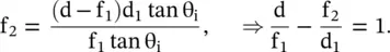
Equation (5.5.31)shows a matched DNG slab has θ i= θ r. For this case, both focal lengths, and also distance D between the object and image at the second focus are given below:
(5.5.35) 
Pendry Superlens Lens
In the case of a DNG‐based matched flat superlens, the image is reconstructed at the second focus by amplification of the evanescent electric fields. Thus, the DNG slab provides an opportunity to design subdiffraction lens, i.e. practically a lens without any diffraction limit. The refractive index of the DNG, matched to air medium, is 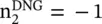 . The longitudinal wavevector k x, given by equation (5.5.28), is rewritten for the backward wave supporting DNG slab as follows [J.2, J.13, J.22]:
(5.5.36) 
The electric fields of both the propagating and evanescent waves, inside the DNG slab, are obtained using the above equations with equation (5.5.29a,b):
(5.5.37) 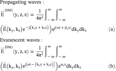
Equation (5.5.37a)shows that the propagating waves acquire the leading phase (β xd) at the end of the DNG slab of thickness x = d. The evanescent waves are amplified exponentially by α xd at the end of the slab. Figure (5.12c)shows such behavior of the DNG based superlens. At the output of the DNG slab, the wave is still evanescent waves in the near‐field region ; although at the image plane its magnitude level is the same as that of at the object plane. So at the second focus, the image has high resolution beyond the diffraction limit. It is noted that the evanescent waves still propagate at the interface along the y‐axis in the (y − z)‐plane as the surface waves . The surface wave is bounded in the x‐direction. The amplification of the evanescent wave is also treated through the concept of coupled quasi‐particles called plasmon‐polariton , especially in the optical frequency range [J.13, B.11].
HyperLens
The anisotropic DNG medium‐based hyperlens converts the evanescent waves to the propagating waves by reducing the values of the transverse wavenumber below the wavenumber in the medium. It is realized by the hyperbolic dispersion relation of the uniaxial anisotropic medium discussed in section ( 4.7.5) of chapter 4. Thus, a hyperlens projects the high‐resolution image in the far‐field region. It is shown in Fig (5.12d). The hyperlens has been realized in the cylindrical geometry using very thin alternate curved layers of conducting and dielectric films. The object is placed at the center and the propagating waves are available at the flat end of the cylindrical medium in which the hyperlens is embedded. The normal optical lens, attached with the hyperlens, carries out the optical processing to create the high‐resolution image in the far‐field region [J.17, J.18].
5.5.7 Doppler and Cerenkov Radiation in DNG Medium
The DNG medium acts inversely on Doppler and Cerenkov radiations. It is examined below.
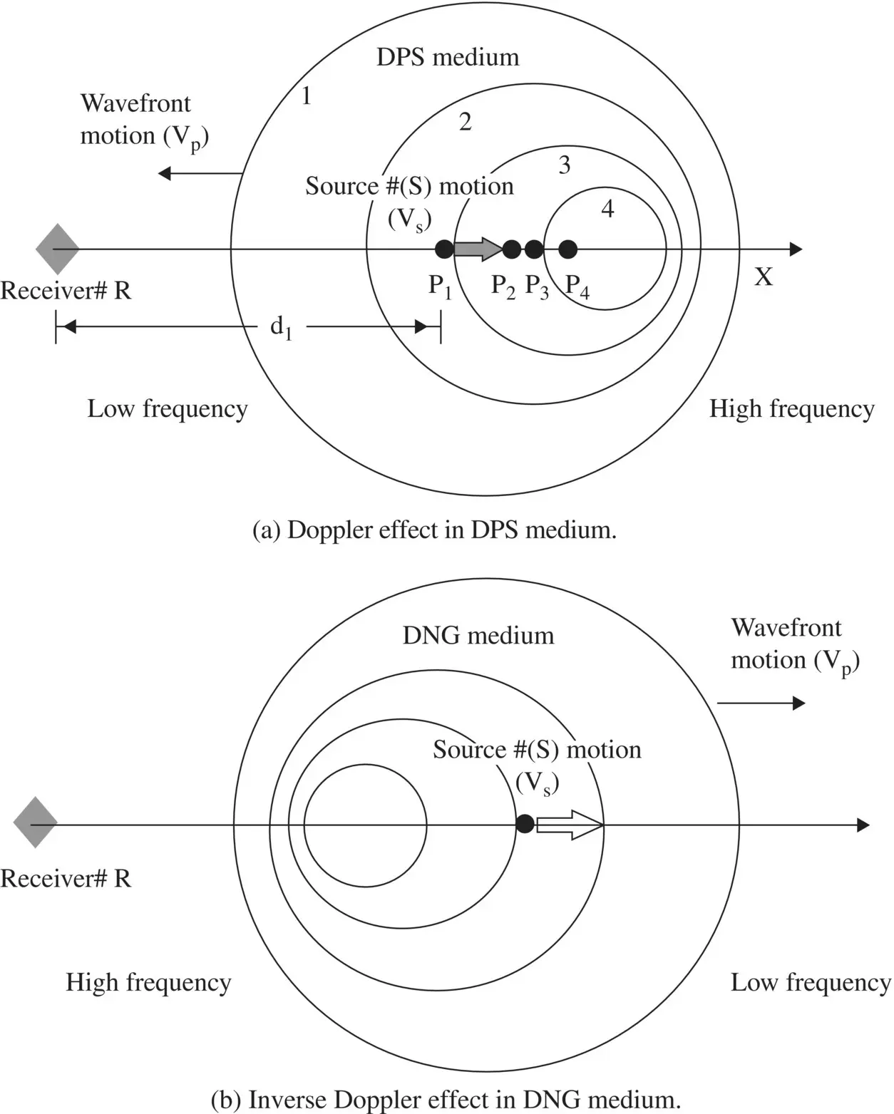
Figure 5.14 Doppler effect in the DPS and DNG media. The source receding the receiver.
Doppler Effect
Doppler effect is related to the change in frequency of a source due to the relative motion of the source and receiver. If a source is moving away, i.e. receding, from the receiver in a DPS medium, the received frequency is less than the stationary frequency of the source. However, if the source is moving toward the receiver, the received frequency is increased.
Let us examine the receding case of a moving source. Figure (5.14a)shows that a source # Sis moving away from receiver #R with velocity V salong the positive x‐axis. The source occupies positions P 1(x = d 1) and P 2(x = d 2) at time t 1and t 2(t 2> t 1), respectively. The source S radiates frequency f sand the radiated spherical wave propagates with the phase velocity V pin the DPS medium . Figure (5.14a)shows the spherical wavefronts at time t 1,…,t 4. The phase of the received wave at time t 1and t 2could be written as
(5.5.38) 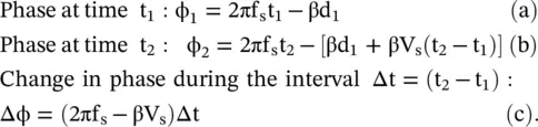
The received frequency f Rof the wave at the stationary receiver is the rate of change in phase, i.e. ω R= 2πf R= Lt Δt → 0(Δϕ/Δt). The received frequency, from the above expression (5.5.38c)is obtained as
(5.5.39) 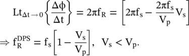
Inverse Doppler Effect
The DNG medium, shown in Fig (5.14b), supports the backward wave propagation with opposite phase velocity. In this case, the spherical wavefronts move in the backward direction. Equation (5.5.39)is used to get the frequency of the received waves from a source moving away from the receiver in the DNG medium:
(5.5.40) 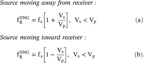
The received frequency of the radiated waves from a source, moving towards the receiver, is reduced at the stationary receiver. In the case, the source is moving away from the receiver, the received frequency increases as 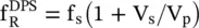 .
.
Due to the reversal of the change in the received frequency, the DNG medium supports the inverse Doppler Effect [J.6]. It has been experimentally confirmed both in the microwave and optical frequency ranges. The inverse Doppler Effect could be used to design tunable and multifrequency radiation sources [J.23–J.25].
Cerenkov Radiation
The Cerenkov radiation, also called the Cherenkov (or Cherenkov) radiation, in the DPS medium is generated from the charged particles traveling with a velocity faster than the velocity of the EM‐wave in that medium [B.12]. The radiation from a leaky‐wave antenna closely follows the radiation mechanism of Cerenkov radiation. Likewise, the planar transmission lines radiate the Cerenkov type radiation within a substrate resulting in high substrate loss [B.13]. It is discussed in subsection (9.7.3) of chapter 9. In a DPS medium the directions of the radiated power, i.e. the direction of the Poynting vector, and the wavevector are in the same direction. However, in a DNG medium, these directions are opposite to each other, giving inverse Cerenkov radiation [J.3]. Both Cerenkov radiation and inverse Cerenkov radiation are similar to the shock waves of supersonics generating the radiation cone.
Читать дальшеИнтервал:
Закладка:
Похожие книги на «Introduction To Modern Planar Transmission Lines»
Представляем Вашему вниманию похожие книги на «Introduction To Modern Planar Transmission Lines» списком для выбора. Мы отобрали схожую по названию и смыслу литературу в надежде предоставить читателям больше вариантов отыскать новые, интересные, ещё непрочитанные произведения.


Обсуждение, отзывы о книге «Introduction To Modern Planar Transmission Lines» и просто собственные мнения читателей. Оставьте ваши комментарии, напишите, что Вы думаете о произведении, его смысле или главных героях. Укажите что конкретно понравилось, а что нет, и почему Вы так считаете.