Anand K. Verma - Introduction To Modern Planar Transmission Lines
Здесь есть возможность читать онлайн «Anand K. Verma - Introduction To Modern Planar Transmission Lines» — ознакомительный отрывок электронной книги совершенно бесплатно, а после прочтения отрывка купить полную версию. В некоторых случаях можно слушать аудио, скачать через торрент в формате fb2 и присутствует краткое содержание. Жанр: unrecognised, на английском языке. Описание произведения, (предисловие) а так же отзывы посетителей доступны на портале библиотеки ЛибКат.

- Название:Introduction To Modern Planar Transmission Lines
- Автор:
- Жанр:
- Год:неизвестен
- ISBN:нет данных
- Рейтинг книги:4 / 5. Голосов: 1
-
Избранное:Добавить в избранное
- Отзывы:
-
Ваша оценка:
Introduction To Modern Planar Transmission Lines: краткое содержание, описание и аннотация
Предлагаем к чтению аннотацию, описание, краткое содержание или предисловие (зависит от того, что написал сам автор книги «Introduction To Modern Planar Transmission Lines»). Если вы не нашли необходимую информацию о книге — напишите в комментариях, мы постараемся отыскать её.
rovides a comprehensive discussion of planar transmission lines and their applications, focusing on physical understanding, analytical approach, and circuit models
Planar transmission lines form the core of the modern high-frequency communication, computer, and other related technology. This advanced text gives a complete overview of the technology and acts as a comprehensive tool for radio frequency (RF) engineers that reflects a linear discussion of the subject from fundamentals to more complex arguments.
Introduction to Modern Planar Transmission Lines: Physical, Analytical, and Circuit Models Approach Emphasizes modeling using physical concepts, circuit-models, closed-form expressions, and full derivation of a large number of expressions Explains advanced mathematical treatment, such as the variation method, conformal mapping method, and SDA Connects each section of the text with forward and backward cross-referencing to aid in personalized self-study
is an ideal book for senior undergraduate and graduate students of the subject. It will also appeal to new researchers with the inter-disciplinary background, as well as to engineers and professionals in industries utilizing RF/microwave technologies.
Introduction To Modern Planar Transmission Lines — читать онлайн ознакомительный отрывок
Ниже представлен текст книги, разбитый по страницам. Система сохранения места последней прочитанной страницы, позволяет с удобством читать онлайн бесплатно книгу «Introduction To Modern Planar Transmission Lines», без необходимости каждый раз заново искать на чём Вы остановились. Поставьте закладку, и сможете в любой момент перейти на страницу, на которой закончили чтение.
Интервал:
Закладка:
The equivalent LC transmission line is an analog of the DPS medium. Therefore, the medium parameters μ and ε could be treated through the analogous series inductance L, and shunt capacitance C, i.e. L → μ, C → ε. The expressions L = Z(ω)/jω and C = Y(ω)/jω for series inductance and shunt capacitance, respectively, model the DPS medium parameters as follows:
(5.5.13) 
In equation (5.5.13), Z(ω) and Y(ω) are the series impedance and shunt admittance of the equivalent line.
Following the above discussion, a DNG medium, supporting the backward‐wave propagation, could be modeled through the CL‐line, shown in Fig ( 3.28b)of chapter 3. Using the above expressions, the material parameters of a DNG medium could be modeled as follows:
(5.5.14) 
The above expressions show that the CL‐line model provides negative values for the permeability and permittivity, as needed for a DNG medium. The characteristic impedance and the propagation constant of the EM‐wave in a DNG medium follows from the above equations:
(5.5.15) 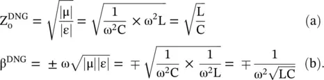
Expression (5.5.15b)shows that even a lossless DNG medium is highly dispersive due to the presence of a term ω 2 in the denominator. It is unlike a DPS medium which is nondispersive for the lossless case . However, a dispersive medium is always associated with loss to meet the Kramer–Kronig condition of causality. It is discussed in subsection (6.5.4) of chapter 6. The causality fails for a fictitious nondispersive DNG medium. The discussion shows that the DNG medium parameters and wavenumber, i.e. ε r, μ r, n, k, are complex quantities [J.8].
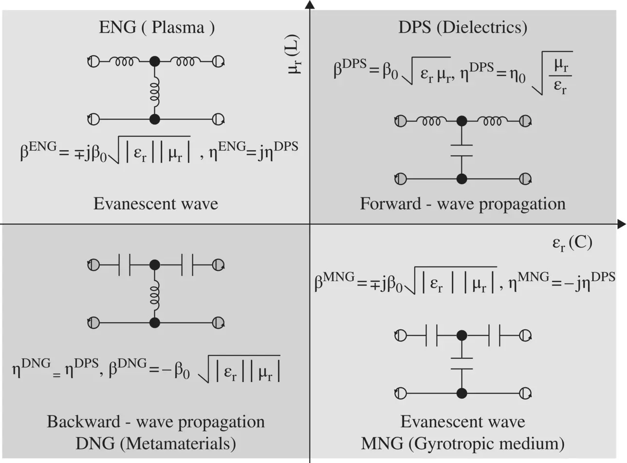
Figure 5.10 Circuit models of four kinds of the medium on the (μ, ε)‐plane.
The DPS transmission line LC‐model can also be extended to the ENG and MNG media. Both these media do not support any EM‐wave propagation. Only the decaying evanescent mode is supported by them, as these media are reactive. The ENG medium is obtained for −ε rand +μ rthat correspond to negative shunt capacitance and positive series inductance. Likewise, the MNG medium is obtained for −μ rand +ε r, i.e. for negative series inductance and positive shunt capacitance. However, the negative capacitance and negative inductance in reality correspond to equivalent positive inductance and equivalent positive capacitance, respectively. It is shown below from their reactance:
(5.5.16) 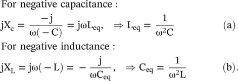
Figure (5.10)shows the equivalent T‐network unit cell for all four kinds of media in the (ε r, μ r)‐plane, i.e. in the corresponding (C, L)‐plane. The ε r(C)‐axis and μ r(L)‐axis show the capacitive shunt element and the inductive series element of the equivalent T‐network of material media. The DPS medium in the first quadrant is changed to the ENG medium by taking a negative value for shunt capacitance that corresponds to a shunt inductor. The L‐L network in the second quadrant corresponds to the ENG medium. The MNG medium is obtained by taking a negative value for the series inductance of the DPS medium. It results in the C‐C network in the fourth quadrant. The characteristics impedance of the ENG and MNG equivalent lines are inductive and capacitive respectively. Of course, by taking negative values for both the series inductance and shunt capacitance of the DPS medium, the DNG medium is created. It is shown as a CL unit cell in the third quadrant of Fig (5.10). Individually, the ENG and MNG media do not support EM‐wave propagation. However, jointly they form a transparent medium, and EM‐wave propagates through the joint medium. It is known as the tunneling phenomenon [J.10, J.11].
The above description of circuit modeling is also applicable to a waveguide below the cut‐off frequency. The TE‐mode waveguide below cut‐off frequency provides the inductive load. So it could be viewed as an ENG medium, while the TM‐mode waveguide below the cut‐off frequency provides the capacitive load and it could be viewed as the MNG medium [B.6, B.8]. The behavior of the modal wave impedance of a rectangular waveguide below the cut‐off frequency is discussed in subsection (7.4.1) of chapter 7.
5.5.4 Lossy DPS and DNG Media
A lossy DPS medium is characterized by the complex permittivity and complex permeability  and
and 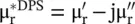 , also
  and
and  . The complex wavenumber for the EM‐wave in a lossy DPS medium is obtained as follows:
(5.5.17) 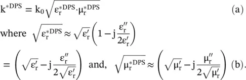
(5.5.18) 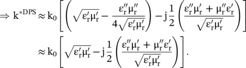
On separating the real and imaginary parts of a complex wavenumber in the DPS medium, k *DPS= k′ − jk ″, the following expressions are obtained:
(5.5.19) 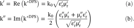
The DPS medium has  . So using the above equations, it is obvious that k '> 0, k ″> 0.
The above expressions are also valid for the DNG medium with some modifications. In the case of a DNG medium, the medium parameters are  . However, even in the DNG medium, the electric and magnetic losses are positive quantities , i.e.
  . Using equation (5.5.19), the complex wavenumber in the DNG is given as follows:
Интервал:
Закладка:
Похожие книги на «Introduction To Modern Planar Transmission Lines»
Представляем Вашему вниманию похожие книги на «Introduction To Modern Planar Transmission Lines» списком для выбора. Мы отобрали схожую по названию и смыслу литературу в надежде предоставить читателям больше вариантов отыскать новые, интересные, ещё непрочитанные произведения.


Обсуждение, отзывы о книге «Introduction To Modern Planar Transmission Lines» и просто собственные мнения читателей. Оставьте ваши комментарии, напишите, что Вы думаете о произведении, его смысле или главных героях. Укажите что конкретно понравилось, а что нет, и почему Вы так считаете.