Anand K. Verma - Introduction To Modern Planar Transmission Lines
Здесь есть возможность читать онлайн «Anand K. Verma - Introduction To Modern Planar Transmission Lines» — ознакомительный отрывок электронной книги совершенно бесплатно, а после прочтения отрывка купить полную версию. В некоторых случаях можно слушать аудио, скачать через торрент в формате fb2 и присутствует краткое содержание. Жанр: unrecognised, на английском языке. Описание произведения, (предисловие) а так же отзывы посетителей доступны на портале библиотеки ЛибКат.

- Название:Introduction To Modern Planar Transmission Lines
- Автор:
- Жанр:
- Год:неизвестен
- ISBN:нет данных
- Рейтинг книги:4 / 5. Голосов: 1
-
Избранное:Добавить в избранное
- Отзывы:
-
Ваша оценка:
Introduction To Modern Planar Transmission Lines: краткое содержание, описание и аннотация
Предлагаем к чтению аннотацию, описание, краткое содержание или предисловие (зависит от того, что написал сам автор книги «Introduction To Modern Planar Transmission Lines»). Если вы не нашли необходимую информацию о книге — напишите в комментариях, мы постараемся отыскать её.
rovides a comprehensive discussion of planar transmission lines and their applications, focusing on physical understanding, analytical approach, and circuit models
Planar transmission lines form the core of the modern high-frequency communication, computer, and other related technology. This advanced text gives a complete overview of the technology and acts as a comprehensive tool for radio frequency (RF) engineers that reflects a linear discussion of the subject from fundamentals to more complex arguments.
Introduction to Modern Planar Transmission Lines: Physical, Analytical, and Circuit Models Approach Emphasizes modeling using physical concepts, circuit-models, closed-form expressions, and full derivation of a large number of expressions Explains advanced mathematical treatment, such as the variation method, conformal mapping method, and SDA Connects each section of the text with forward and backward cross-referencing to aid in personalized self-study
is an ideal book for senior undergraduate and graduate students of the subject. It will also appeal to new researchers with the inter-disciplinary background, as well as to engineers and professionals in industries utilizing RF/microwave technologies.
Introduction To Modern Planar Transmission Lines — читать онлайн ознакомительный отрывок
Ниже представлен текст книги, разбитый по страницам. Система сохранения места последней прочитанной страницы, позволяет с удобством читать онлайн бесплатно книгу «Introduction To Modern Planar Transmission Lines», без необходимости каждый раз заново искать на чём Вы остановились. Поставьте закладку, и сможете в любой момент перейти на страницу, на которой закончили чтение.
Интервал:
Закладка:
On solving the above last two equations, the reflection coefficient Γ, and the transmission coefficient τ are computed at the interface:
(5.1.3) 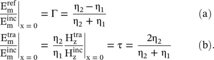
For a lossy medium, the intrinsic impedance is a complex quantity, and reflection and transmission coefficients are also complex quantities. However, the magnitude of the reflection coefficient of a passive medium is always equal to or less than unity, i.e. |Γ| ≤ 1. The magnitude and phase of the reflected and transmitted waves are different from that of the incident waves. For a lossless composite medium, the matching is obtained, i.e. no reflection Γ = 0, for an incident wave at the interface with η 1= η 2. It could be realized in two ways:
(5.1.4) 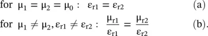
In equations (5.1.4a,b), the first case is the usual one, as both media are identical. However, the second case is interesting; as the matching is possible even for dissimilar media. It may not be a practical one with natural materials. However, for the artificially engineered metamaterials , both μ rand ε rcan be tuned independently to achieve the matching condition, It is discussed in sub section (5.5.8). The impedance‐matched Huygens' metasurface has also been developed by tuning of electric and magnetic inclusions discussed in subsection (22.5.2) of chapter 22.
Sometimes, the concept of the reflectance (reflectivity) R and transmittance (transmissivity) T are used to show the portion of the reflected and transmitted powers:
(5.1.5) 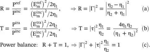
The total field in medium #1 is a combination of the incident and reflected waves causing interference of waves. The field is uniform in the x ‐direction. However, it creates partly a standing wave, and partly the traveling wave moving in the x ‐direction:
(5.1.6) 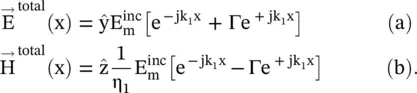
For Γ > 0, i.e. for η 2> η 1, the above expression can be decomposed as follows:
(5.1.7) 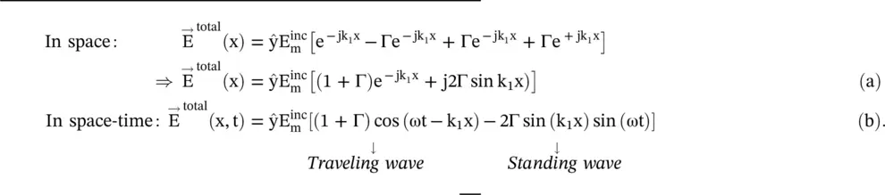
In equation (5.1.7), 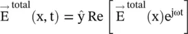 is taken.
Likewise, for Γ < 0, i.e. for η 2< η 1, the wave in the medium can be written as follows:
(5.1.8) 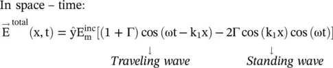
The combined traveling and standing wave description follow a similar condition on a mismatched line given by equation ( 2.1.89) of chapter 2. Using the phasor – (5.1.6a), the  occurs for
  and
and  occur for
  , where n = 0,1,2,…. The VSWR in the medium is obtained as follows:
(5.1.9) 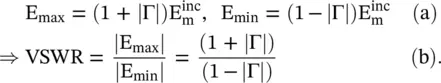
The power densities in medium #1 (x<0) and #2 (x>0) are obtained using Poynting vector relation:
(5.1.10) 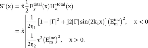
The time‐averaged power density is a real part of S *(x):
(5.1.11) 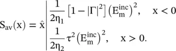
In the case of a lossless composite medium, the power balance is maintained. It is seen by separating the incident, reflected, and transmitted power densities:
(5.1.12) 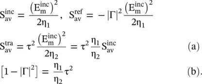
Equation (5.1.12b)has been also obtained in equation (5.1.5c)from the concept of reflectance and transmittance. The above relation shows that the power balance Γ 2+ τ 2= 1 does not hold in the present case. The modified power balance relation is given by equation (5.1.12b). It shows that the transmission coefficient could be even more than unity, as it is multiplied by a factor  However, the above‐given power balance relation must be maintained [B.1].
5.1.2 The Interface of a Dielectric and Perfect Conductor
Medium #2 could be a conducting medium, with the intrinsic impedance,  For a PEC medium, σ → ∞ , η 2→ 0.The PEC has infinite permittivity, i.e. ε → ∞. Using equation (5.1.3a), the interface provides the total reflection with the reflection coefficient Γ = − 1; i.e. a phase reversal for the reflected
  component. The total tangential electric field at the interface (x = 0 −) is zero. There is no field in the medium #2. The total electric field, using an equation (5.1.6a), in medium #1 is,
(5.1.13) 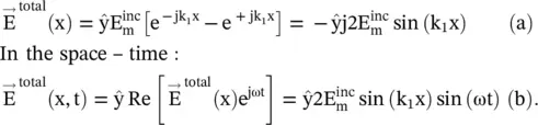
The expression (5.1.13)shows the formation of a standing wave in the medium #1, without any traveling wave. The standing wave for the H zfield component can be easily obtained. At the PEC surface, the E y‐field is zero, and H z‐field is at maximum.
The total reflection at the interface also occurs for η 2→ ∞ , i. e. for μ → ∞. In this case, medium #2 acts as a PMC, and it offers Γ = + 1. The PMC has infinite permeability, i.e. μ → ∞. Again, a standing wave is formed in the medium #1, with E y‐field maximum at the interface; while H zis zero. The PMC is a hypothetical medium. However, it is realized on the periodically loaded surface as an artificial magnetic conductor (AMC) over a band of frequencies. The interface can also totally reflect the wave if the interface offers either inductive or capacitive impedance. In this case, the interface is a RIS. The periodic surfaces are discussed in chapter 20. These are widely used in the modern microwave and antenna engineering. The PEC, and PMC surfaces, forming the idealized rectangular waveguides, are discussed in chapter 7.
Читать дальшеИнтервал:
Закладка:
Похожие книги на «Introduction To Modern Planar Transmission Lines»
Представляем Вашему вниманию похожие книги на «Introduction To Modern Planar Transmission Lines» списком для выбора. Мы отобрали схожую по названию и смыслу литературу в надежде предоставить читателям больше вариантов отыскать новые, интересные, ещё непрочитанные произведения.


Обсуждение, отзывы о книге «Introduction To Modern Planar Transmission Lines» и просто собственные мнения читателей. Оставьте ваши комментарии, напишите, что Вы думаете о произведении, его смысле или главных героях. Укажите что конкретно понравилось, а что нет, и почему Вы так считаете.