Anand K. Verma - Introduction To Modern Planar Transmission Lines
Здесь есть возможность читать онлайн «Anand K. Verma - Introduction To Modern Planar Transmission Lines» — ознакомительный отрывок электронной книги совершенно бесплатно, а после прочтения отрывка купить полную версию. В некоторых случаях можно слушать аудио, скачать через торрент в формате fb2 и присутствует краткое содержание. Жанр: unrecognised, на английском языке. Описание произведения, (предисловие) а так же отзывы посетителей доступны на портале библиотеки ЛибКат.

- Название:Introduction To Modern Planar Transmission Lines
- Автор:
- Жанр:
- Год:неизвестен
- ISBN:нет данных
- Рейтинг книги:4 / 5. Голосов: 1
-
Избранное:Добавить в избранное
- Отзывы:
-
Ваша оценка:
Introduction To Modern Planar Transmission Lines: краткое содержание, описание и аннотация
Предлагаем к чтению аннотацию, описание, краткое содержание или предисловие (зависит от того, что написал сам автор книги «Introduction To Modern Planar Transmission Lines»). Если вы не нашли необходимую информацию о книге — напишите в комментариях, мы постараемся отыскать её.
rovides a comprehensive discussion of planar transmission lines and their applications, focusing on physical understanding, analytical approach, and circuit models
Planar transmission lines form the core of the modern high-frequency communication, computer, and other related technology. This advanced text gives a complete overview of the technology and acts as a comprehensive tool for radio frequency (RF) engineers that reflects a linear discussion of the subject from fundamentals to more complex arguments.
Introduction to Modern Planar Transmission Lines: Physical, Analytical, and Circuit Models Approach Emphasizes modeling using physical concepts, circuit-models, closed-form expressions, and full derivation of a large number of expressions Explains advanced mathematical treatment, such as the variation method, conformal mapping method, and SDA Connects each section of the text with forward and backward cross-referencing to aid in personalized self-study
is an ideal book for senior undergraduate and graduate students of the subject. It will also appeal to new researchers with the inter-disciplinary background, as well as to engineers and professionals in industries utilizing RF/microwave technologies.
Introduction To Modern Planar Transmission Lines — читать онлайн ознакомительный отрывок
Ниже представлен текст книги, разбитый по страницам. Система сохранения места последней прочитанной страницы, позволяет с удобством читать онлайн бесплатно книгу «Introduction To Modern Planar Transmission Lines», без необходимости каждый раз заново искать на чём Вы остановились. Поставьте закладку, и сможете в любой момент перейти на страницу, на которой закончили чтение.
Интервал:
Закладка:
(5.2.6) 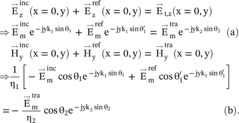
The fields are complex quantities on both the left and right‐hand sides of the interface. To match the fields at the interface, i.e. along the y ‐axis, both the phase and amplitude matching are needed. The continuity equation, given by equation (5.2.6a), holds at all points along the interface, i.e. along the y ‐axis. To achieve it, the exponential terms, giving phases of the incident, reflected, and refracted waves must be identical. It is known as the phase matching at the interface. The phase‐matching results in the following well‐known Snell's laws of reflection and refraction:
(5.2.7) 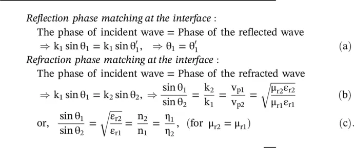
Equation (5.2.7b)is used for a magnetodielectric medium, whereas equation (5.2.7c)is valid for a dielectric medium. The n 1and n 2are the refractive indexes, whereas η 1and η 2are the intrinsic impedance of the medium #1, and medium #2, respectively. Moreover, the classical Snell's laws are obtained under the condition of the uniform phase at the interface in the direction of the y ‐axis. However, the phase gradient dϕ/dy can be created on an interface of the engineered metasurface . In this case, the classical Snell's laws are modified to obtain the generalized Snell's laws. It is discussed in subsection (22.5.4) of chapter 22.
The amplitude matching of the tangential components of the E and H‐fields at the interface x = 0, from equation (5.2.6), provides the following expressions for the reflection (  ) and transmission (
  ) coefficients of the perpendicular (TE) polarized obliquely incident plane waves:
(5.2.8) 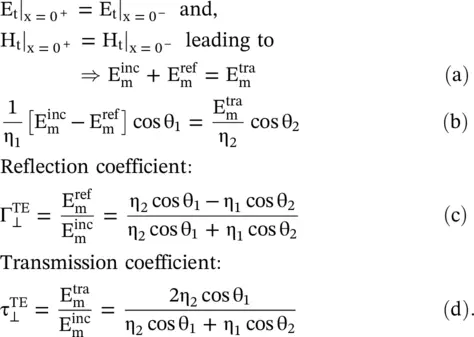
Equations (5.2c,d) are known as the Fresnel's Equations of the TE‐polarized waves. They describe the ratio of the reflected and transmitted electric fields to that of the incident electric field. As the reflection and transmission coefficients are complex quantities, they describe both the relative amplitude and phase shifts between the waves. The above equations show that if both media are identical; there is no reflection, Γ ⊥= 0; and η 1= η 2, θ 1= θ 2, leading to total transmission τ ⊥= 1. It is also noted that τ ⊥ TE= 1 + Γ ⊥ TE.
The total field component in the medium #1 is a summation of the incident and reflected fields, given by equations while in the medium #2, only a refracted field, given by equation (5.2.4)exists. These field equations are summarized below:
Medium #1
(5.2.9) 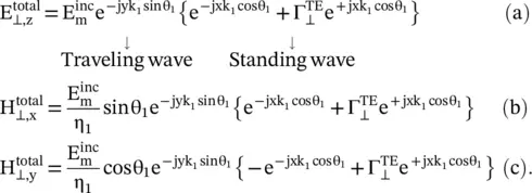
Medium #2
(5.2.10) 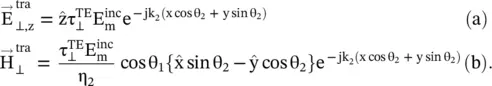
In medium #1, due to the superposition of incident and reflected waves, interference occurs. Following the process used in equation (5.1.7), the computed total wave is partly traveling wave along the y ‐axis, while along the negative x ‐axis, it is partly standing wave. However, the minima of the standing wave do not reach zero levels as Γ ⊥≠ − 1, like a PEC. Although, the wave is traveling along the interface in the y ‐direction, still the wave is not the surface wave , as in the x‐direction the field is not confined to the surface. Under certain conditions, discussed in sub section (5.3.2), propagation of the surface wave is possible. The surface wave is further discussed in section (7.5) of chapter 7.
The Oblique Incidence on a Perfect Electric Conductor
If the medium #2 is a PEC, i.e. η 2= 0, ε r2= ∞, the reflection coefficient is  . The total field components, in the medium #1, are given below from equation (5.2.9); while in the medium #2 there is no field:
(5.2.11) 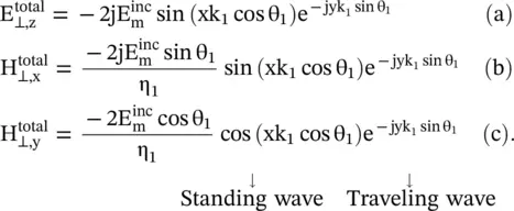
In equation (5.2.11a, b, c)harmonic‐time dependence e jωtis suppressed. It is seen from equations (5.2.11a, b, c)that the interference produces a total wavefield moving in the y‐direction along the interface, while along the direction of the normal, i.e. in the x‐direction, it is a standing wave. It shows that the interference field pattern is traveling along the interface.
5.2.2 TM (Parallel) Polarization Case
Figure (5.3a)shows an oblique incidence of TM z‐polarized plane wave ray at the interface of two electrically different media. The electric field of the incident wave is in the (x‐y)‐ plane of incidence, so the incident wave has a parallel polarization as the E incfield is parallel to the plane of incidence. The parallel polarization , or p‐polarization , is also known as the transverse magnetic (TM) polarization as the z‐oriented magnetic field is normal to the plane of incidence. It is also called π ‐polarization .
The visual inspection of the direction of field vectors in Fig (5.3a)shows that the magnetic field component H zis normal to the (x − y)‐plane, i.e. to the plane of polarization, while the electric field components E xand E yare in the plane of polarization. The field components of the incident, reflected, and transmitted ( refracted ) TM‐polarized obliquely incident wave, as shown in Fig (5.3a), are summarized below:
(5.2.12) 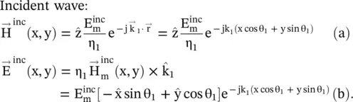
(5.2.13) 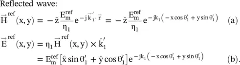
Transmitted wave:
(5.2.14) 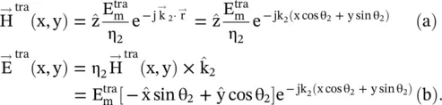
The continuity of the tangential electric and magnetic field components, across the interface at x = 0, provides the following expression:
(5.2.15) 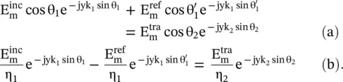
The Poynting vectors are the same as that of the TE‐polarization. The phase matching, from equation (5.2.15), again provides Snell's reflection and refractions laws as given by equation (5.2.7). However, the amplitude matching provides different expressions for the reflection (Γ ll TM), and transmission τ ll TMcoefficients of the parallel polarized obliquely incident plane wave:
Читать дальшеИнтервал:
Закладка:
Похожие книги на «Introduction To Modern Planar Transmission Lines»
Представляем Вашему вниманию похожие книги на «Introduction To Modern Planar Transmission Lines» списком для выбора. Мы отобрали схожую по названию и смыслу литературу в надежде предоставить читателям больше вариантов отыскать новые, интересные, ещё непрочитанные произведения.


Обсуждение, отзывы о книге «Introduction To Modern Planar Transmission Lines» и просто собственные мнения читателей. Оставьте ваши комментарии, напишите, что Вы думаете о произведении, его смысле или главных героях. Укажите что конкретно понравилось, а что нет, и почему Вы так считаете.