Mantle Convection and Surface Expressions
Здесь есть возможность читать онлайн «Mantle Convection and Surface Expressions» — ознакомительный отрывок электронной книги совершенно бесплатно, а после прочтения отрывка купить полную версию. В некоторых случаях можно слушать аудио, скачать через торрент в формате fb2 и присутствует краткое содержание. Жанр: unrecognised, на английском языке. Описание произведения, (предисловие) а так же отзывы посетителей доступны на портале библиотеки ЛибКат.

- Название:Mantle Convection and Surface Expressions
- Автор:
- Жанр:
- Год:неизвестен
- ISBN:нет данных
- Рейтинг книги:4 / 5. Голосов: 1
-
Избранное:Добавить в избранное
- Отзывы:
-
Ваша оценка:
Mantle Convection and Surface Expressions: краткое содержание, описание и аннотация
Предлагаем к чтению аннотацию, описание, краткое содержание или предисловие (зависит от того, что написал сам автор книги «Mantle Convection and Surface Expressions»). Если вы не нашли необходимую информацию о книге — напишите в комментариях, мы постараемся отыскать её.
Mantle Convection and Surface Expressions Volume highlights include:
Perspectives from different scientific disciplines with an emphasis on exploring synergies Current state of the mantle, its physical properties, compositional structure, and dynamic evolution Transport of heat and material through the mantle as constrained by geophysical observations, geochemical data and geodynamic model predictions Surface expressions of mantle dynamics and its control on planetary evolution and habitability The American Geophysical Union promotes discovery in Earth and space science for the benefit of humanity. Its publications disseminate scientific knowledge and provide resources for researchers, students, and professionals.
Mantle Convection and Surface Expressions — читать онлайн ознакомительный отрывок
Ниже представлен текст книги, разбитый по страницам. Система сохранения места последней прочитанной страницы, позволяет с удобством читать онлайн бесплатно книгу «Mantle Convection and Surface Expressions», без необходимости каждый раз заново искать на чём Вы остановились. Поставьте закладку, и сможете в любой момент перейти на страницу, на которой закончили чтение.
Интервал:
Закладка:
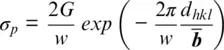
where G is the shear modulus, w is a term that depends on the dislocation character (screw vs. edge), d hklis the lattice spacing of the glide plane and  is the Burgers vector. The Burgers vector gives the magnitude and direction of lattice distortion resulting from a dislocation. A few general trends can be seen from this formulation. If G is large, then σ p∝ elastic properties. Since G in minerals is strongly dependent on pressure, the strength of minerals, likewise, is strongly dependent on pressure. The term
  is sometimes used to predict which glide plane should be favored as a large d hkland short
  should result in a lower Peierls stress. However, caution should be used when applying this to minerals, as the above formulation is derived for a monoatomic lattice. Minerals, in contrast, have mixed bond strength and often do not follow this rule. Recent developments have allowed calculation of lattice friction for minerals over a wide range of conditions using the Peierls‐Nabarro model (e.g., Carrez et al., 2007a; Cordier & Goryaeva, 2018). Of particular importance, to the following discussion is that dislocation activity leads to grain rotation, which results in texture. Texture frequently leads to anisotropic bulk physical properties of polycrystals.
At stress conditions, intermediate to dislocation glide and diffusion creep, deformation is dominated by dislocation creep, i.e., glide accommodated by climb via diffusion. When dislocation glide alone is active, dislocations can interact and encounter obstacles to dislocation motion, which results in hardening. When stresses are low (typically due to high temperature and/or slow strain rates), dislocations can climb (diffuse) out of plane to bypass obstacles. Depending on ease of climb, various forms of constitutive laws can be written (Weertman, 1970; Weertman & Weertman, 1975). These lead to a nonlinear stress–strain rate relationship where  ∝ σ nand n = 3–5. Notably, there is no grain size dependence.
Frequently a general constitutive equation is used that can capture both diffusion and dislocation creep (Hirth & Kohlstedt, 2003):
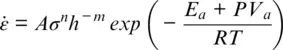
where A is an empirically determined pre‐exponential factor. For diffusion creep, n is 1 and m is 2–3, and for dislocation creep n is typically 3–5 and m = 0.
While it is relatively straightforward to determine deformation mechanisms in the laboratory, it is much harder to determine operative mechanisms in the deep Earth. For crustal and upper mantle rocks, microstructural signatures of deformation can be observed and provide constraints on active deformation mechanisms (e.g., Knipe, 1989; Park & Jung, 2017; Passchier & Trouw, 2005). However, for the lower mantle natural samples of sufficient size to study and determine deformation mechanisms are not available, and deformation mechanisms must be inferred indirectly. Seismic observations are one of the few methods to image the Earth’s deep interior, and seismic anisotropy can provide clues to deformation mechanisms in the deep Earth. Seismic anisotropy is generally attributed to texture development due to plastic deformation by dislocation creep. It is generally assumed that if there is no anisotropy, diffusion creep is operative, as in most case diffusion creep does not induce texture. Conversely, the general assumption is that if seismic anisotropy is observed, dislocation creep is likely (see Karato (2010) for a discussion of potential deformation mechanism in the mantle).
Note that a few cases have been observed where texture does develop in minerals deformed in diffusion creep, as defined by Newtonian rheology ( n = 1). These are generally samples that have been deformed near the transition between diffusion creep and dislocation creep (e.g., Barreiro et al., 2007), unusual cases in the presence of fluid/melt (Bons & den Brok, 2000), or due to strongly anisotropic grain shapes (Miyazaki et al., 2013; Yoshizawa et al., 2004). One should also recognize that deformation by diffusion and dislocations are competing processes and that both diffusion creep and dislocation creep can operate simultaneously in the same sample.
In the lower mantle, seismic anisotropy is observed at the top of the lower mantle near subducting slabs (Ferreira et al., 2019; Lynner & Long, 2015; Mohiuddin et al., 2015; Wookey et al., 2002) and also at the base of the mantle in the D ” region (for recent summaries of D ” anisotropy, see Creasy et al., 2019 and Romanowicz & Wenk, 2017). In contrast to these regions, the bulk of the mantle appears to be seismically isotropic. This has led to the suggestion that the bulk of the mantle deforms by diffusion creep (Karato et al., 1995), whereas regions of high strain near subducting slabs and at boundary layers such as near the CMB undergo deformation by dislocation creep (McNamara et al., 2002). However, others have suggested that isotropy might be due to patterns of anisotropy for Brg and Fp that cancel each other leading to an isotropic aggregate (Wenk, Speziale, et al., 2006). In any case, it appears that dislocation creep is active in at least some regions of the lower mantle, but it might also be likely that the mantle is close to the transition between diffusion creep and dislocation creep. As such, strain rate gradients in the mantle may result in transitions between diffusion‐dominated and dislocation‐dominated regimes.
2.3 METHODS: EXPERIMENTAL DEFORMATION OF LOWER MANTLE MINERALS
Deformation studies of lower mantle phases are complicated by the fact that many phases are unstable (Brg) or unquenchable (Ca‐Pv and pPv) to ambient conditions. Both Ca‐Pv and pPv become amorphous during pressure release and cannot be preserved to ambient pressures. Thus study of recovered samples (from high pressure and/or temperature experiments) is difficult or impossible, necessitating in‐situ analysis. A technique that has led to significant advances in deformation studies of these phases is the use of synchrotron x‐ray diffraction in conjunction with high pressure and temperature deformation devices.
2.3.1 The Diamond Anvil Cell as a Deformation Device
The diamond anvil cell (DAC) uses two gem‐quality diamonds with flat tips (culets) in opposed anvil geometry to generate high confining pressure (e.g., Jayaraman, 1983). In DAC experiments, a tiny sample (< 0.1 mm) is confined within a gasket and the anvils impose pressure and stress on the sample. The DAC is capable of generating pressures in excess of those experienced at the center of the Earth. Most commonly, the DAC is used in axial diffraction geometry where the x‐ray beam is parallel to the compression axis. This is advantageous as the diamonds are nearly x‐ray transparent. In these types of experiments the sample is typically surrounded by a soft pressure medium to reduce differential stress to near hydrostatic conditions. This type of experiment has been highly successful for studying phase equilibria and equations of state at high pressure and temperature. The DAC has also been used in axial geometry without a pressure medium to infer yield strength from radial pressure gradients (e.g., Meade & Jeanloz, 1988).
Читать дальшеИнтервал:
Закладка:
Похожие книги на «Mantle Convection and Surface Expressions»
Представляем Вашему вниманию похожие книги на «Mantle Convection and Surface Expressions» списком для выбора. Мы отобрали схожую по названию и смыслу литературу в надежде предоставить читателям больше вариантов отыскать новые, интересные, ещё непрочитанные произведения.


Обсуждение, отзывы о книге «Mantle Convection and Surface Expressions» и просто собственные мнения читателей. Оставьте ваши комментарии, напишите, что Вы думаете о произведении, его смысле или главных героях. Укажите что конкретно понравилось, а что нет, и почему Вы так считаете.