Gene Cheung - Graph Spectral Image Processing
Здесь есть возможность читать онлайн «Gene Cheung - Graph Spectral Image Processing» — ознакомительный отрывок электронной книги совершенно бесплатно, а после прочтения отрывка купить полную версию. В некоторых случаях можно слушать аудио, скачать через торрент в формате fb2 и присутствует краткое содержание. Жанр: unrecognised, на английском языке. Описание произведения, (предисловие) а так же отзывы посетителей доступны на портале библиотеки ЛибКат.
- Название:Graph Spectral Image Processing
- Автор:
- Жанр:
- Год:неизвестен
- ISBN:нет данных
- Рейтинг книги:5 / 5. Голосов: 1
-
Избранное:Добавить в избранное
- Отзывы:
-
Ваша оценка:
Graph Spectral Image Processing: краткое содержание, описание и аннотация
Предлагаем к чтению аннотацию, описание, краткое содержание или предисловие (зависит от того, что написал сам автор книги «Graph Spectral Image Processing»). Если вы не нашли необходимую информацию о книге — напишите в комментариях, мы постараемся отыскать её.
Graph Spectral Image Processing — читать онлайн ознакомительный отрывок
Ниже представлен текст книги, разбитый по страницам. Система сохранения места последней прочитанной страницы, позволяет с удобством читать онлайн бесплатно книгу «Graph Spectral Image Processing», без необходимости каждый раз заново искать на чём Вы остановились. Поставьте закладку, и сможете в любой момент перейти на страницу, на которой закончили чтение.
Интервал:
Закладка:
The synthesis transform combines  to reconstruct the signal. This is represented as
[1.37] 
where  is the synthesis transform matrix. The perfect reconstruction transform is defined as the transform that recovers the original signal perfectly, when no processing is performed between the analysis and synthesis transforms. Formally, it satisfies the following condition:
[1.38] 
The details of perfect reconstruction graph filter banks are provided in the next section.
While Rcan be arbitrary, one may need a symmetric structure: the synthesis transform represented by multiple filters and upsampling as a counterpart of the analysis transform. In classical signal processing, most filter banks are designed to be symmetric, which, in contrast, is difficult for the graph versions, mainly due to the sampling operations. Several design methods make it possible to design perfect reconstruction graph transforms with a symmetric structure (Narang and Ortega 2012; Narang and Ortega 2013; Shuman et al. 2015; Leonardi and Van De Ville 2013; Tanaka and Sakiyama 2014; Sakiyama and Tanaka 2014; Sakiyama et al. 2016; Sakiyama et al. 2019a; Teke and Vaidyanathan 2016; Sakiyama et al. 2019b).
1.5.2. Perfect reconstruction condition
Suppose that the redundancy is ρ ≥ 1 and the columns of Eare linearly independent. The perfect reconstruction condition equation [1.38]is clearly rewritten as
[1.39] 
The critically sampled system constrains that Eis a square matrix; therefore, Rmust be E −1for perfect reconstruction. For the oversampled system, we generally have an infinite number of Rsatisfying the condition in equation [1.39]. The most simple and well-known solution is the least squares solution, which is expressed as
[1.40] 
This is nothing but the Moore–Penrose pseudo inverse of E 4 . This GSP system is generally asymmetric: while the analysis transform has graph filters and possible sampling, the synthesis transform does not have such a clear notion of filtering and upsampling. In general, the asymmetric structure requires a matrix inversion. Additionally, the N × N matrix E T Eis usually dense, which leads to  complexity.
Therefore, symmetric structures are often desired instead, and they are similar to those that are widely used in classical signal processing. The synthesis transform with a symmetric structure has the following form:
[1.41] 
where g k( L) is the k th synthesis filter and  is an upsampling matrix. As a result, each subband has the following input–output relationship:
[1.42] 
reconstruction, it must be x.The resulting output is therefore represented as  and for perfect reconstruction, it must be x.
1.5.2.1. Design of perfect reconstruction transforms: undecimated case
There are various methods available for designing perfect reconstruction graph transforms. First, let us consider undecimated transforms that exhibit symmetrical structure.
An undecimated transform has no sampling, i.e. S k= I Nfor all k . Therefore, the analysis and synthesis transforms, respectively, are represented in the following simple forms:
[1.43] 
[1.44] 
Accordingly, the perfect reconstruction condition can also be simple. The input–output relationship in equation [1.42]is reduced to
[1.45] 
Assuming p k( L) := g k( L) h k( L) as the k th product filter, the output signal is thus given by
[1.46] 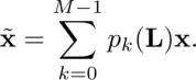
Therefore, the product filters must satisfy the following condition for perfect reconstruction:
[1.47] 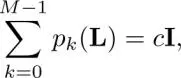
where c is some constant.
Suppose that h k( L) and g k( L) are parameterized as 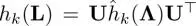 and g k( L) = U ĝ k( Λ) U T, respectively. In this case, equation [1.47]can be further reduced to
[1.48] 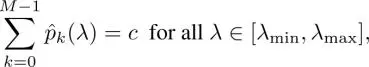
where  This condition is similar to that considered in biorthogonal FIR filter banks in classical signal processing (Vaidyanathan 1993; Vetterli and Kovacevic 1995; Strang and Nguyen 1996). When
  and the filter set satisfies equation [1.48], the filter bank is called a tight frame because the perfect reconstruction condition can be rewritten as
Интервал:
Закладка:
Похожие книги на «Graph Spectral Image Processing»
Представляем Вашему вниманию похожие книги на «Graph Spectral Image Processing» списком для выбора. Мы отобрали схожую по названию и смыслу литературу в надежде предоставить читателям больше вариантов отыскать новые, интересные, ещё непрочитанные произведения.


Обсуждение, отзывы о книге «Graph Spectral Image Processing» и просто собственные мнения читателей. Оставьте ваши комментарии, напишите, что Вы думаете о произведении, его смысле или главных героях. Укажите что конкретно понравилось, а что нет, и почему Вы так считаете.