Ian Smith - Smith's Elements of Soil Mechanics
Здесь есть возможность читать онлайн «Ian Smith - Smith's Elements of Soil Mechanics» — ознакомительный отрывок электронной книги совершенно бесплатно, а после прочтения отрывка купить полную версию. В некоторых случаях можно слушать аудио, скачать через торрент в формате fb2 и присутствует краткое содержание. Жанр: unrecognised, на английском языке. Описание произведения, (предисловие) а так же отзывы посетителей доступны на портале библиотеки ЛибКат.

- Название:Smith's Elements of Soil Mechanics
- Автор:
- Жанр:
- Год:неизвестен
- ISBN:нет данных
- Рейтинг книги:5 / 5. Голосов: 1
-
Избранное:Добавить в избранное
- Отзывы:
-
Ваша оценка:
Smith's Elements of Soil Mechanics: краткое содержание, описание и аннотация
Предлагаем к чтению аннотацию, описание, краткое содержание или предисловие (зависит от того, что написал сам автор книги «Smith's Elements of Soil Mechanics»). Если вы не нашли необходимую информацию о книге — напишите в комментариях, мы постараемся отыскать её.
Smith's Elements of Soil Mechanics — читать онлайн ознакомительный отрывок
Ниже представлен текст книги, разбитый по страницам. Система сохранения места последней прочитанной страницы, позволяет с удобством читать онлайн бесплатно книгу «Smith's Elements of Soil Mechanics», без необходимости каждый раз заново искать на чём Вы остановились. Поставьте закладку, и сможете в любой момент перейти на страницу, на которой закончили чтение.
Интервал:
Закладка:
Example 2.10Seepage loss through dam (iii)
A dam has the same details as in Example 2.8, except that there is no filter drain at the toe. Determine the seepage loss through the dam.
Solution:
The flow net is shown in Fig. 2.29and from it we see N f= 4.0 and N d= 18 (average). From the flow net, it is also seen that a + Δa = 22.4 m. Now α = 45°, and hence:
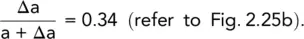
Hence Δa = 7.6 m
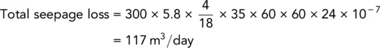
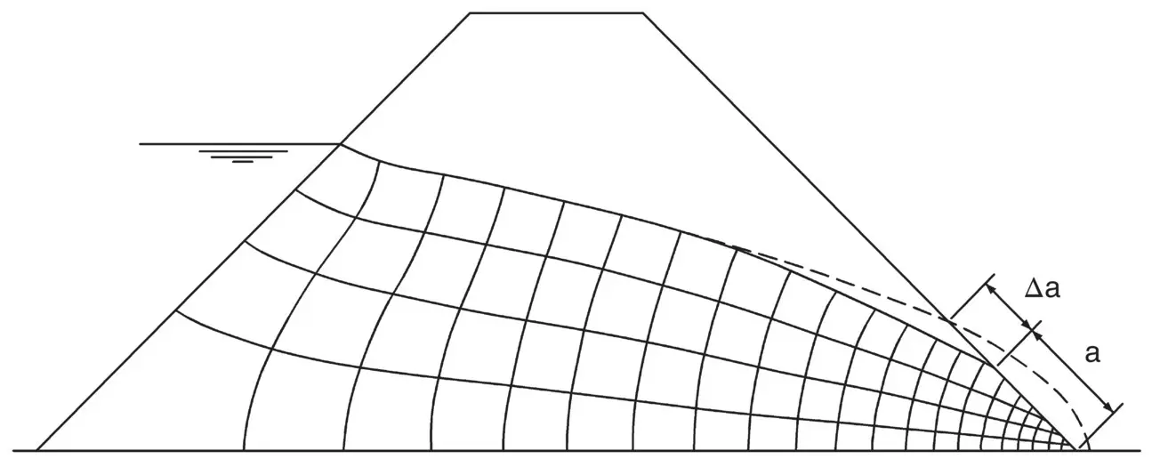
Fig. 2.29 Example 2.10.
2.15.3 Permeability of sedimentary deposits
A sedimentary deposit may consist of several different soils and it is often necessary to determine the average values of permeability in two directions, one parallel to the bedding planes and the other at right angles to them.
Let there be n layers of thicknesses H1, H2, H3, … Hn.
Let the total thickness of the layers be H.
Let k1, k2, k3, … kn be the respective coefficients of permeability for each individual layer.
Let the average permeability for the whole deposit be kx for flow parallel to the bedding planes, and kz for flow perpendicular to this direction.
Consider flow parallel to the bedding planes:

where A = total area and i = hydraulic gradient.
This total flow must equal the sum of the flow through each layer, therefore:

Considering unit width of soil:

hence
(2.34) 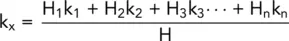
Considering flow perpendicular to the bedding planes:

Considering unit area:

Now
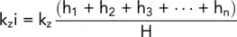
where h 1, h 2, h 3, etc., are the respective head losses across each layer.
Now
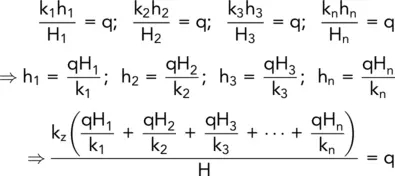
hence
(2.35) 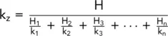
Example 2.11Quantity of flow
A three‐layered soil system consisting of fine sand, coarse silt, and fine silt in horizontal layers is shown in Fig. 2.30.
Beneath the fine silt layer, there is a stratum of water‐bearing gravel with a water pressure of 155 kPa. The surface of the sand is flooded with water to a depth of 1 m.
Determine the quantity of flow per unit area in mm 3/s, and the excess hydraulic heads at the sand/coarse silt and the coarse silt/fine silt interfaces.
Solution:
Taking the top of the gravel as datum:
Head of water due to artesian pressure = 15.5 m
Head of water due to groundwater = 3 × 4 + 1 = 13 m
Therefore, excess head causing flow = 15.5 − 13 = 2.5 m.

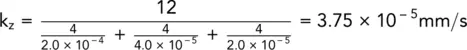
This quantity of flow is the same through each layer.
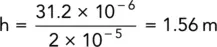
Excess head loss through fine silt:
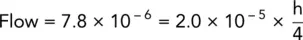
Therefore,
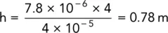
Excess head loss through coarse silt:
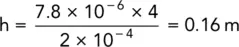
Excess head loss through fine sand:
Excess head at interface between fine and coarse silt

Excess head at interface between fine sand and coarse silt

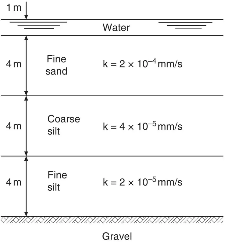
Fig. 2.30 Example 2.11.
2.15.4 Seepage through soils of different permeabilities
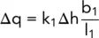
When water seeps from a soil of permeability k 1into a soil of permeability k 2, the principle of the square flow net is no longer valid. If we consider a flow net in which the head drop across each figure, Δh, is a constant then, as has been shown, the flow through each figure is given by the expression:
(2.36) 
If Δq is to remain the same when k is varied, then b/l must also vary. As an illustration of this effect, consider the case of two soils with k 1= k 2/3.
Then
and
(2.37) 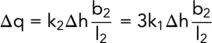
i.e.

If the portion of the flow net in the soil of permeability k 1is square, then:
Читать дальшеИнтервал:
Закладка:
Похожие книги на «Smith's Elements of Soil Mechanics»
Представляем Вашему вниманию похожие книги на «Smith's Elements of Soil Mechanics» списком для выбора. Мы отобрали схожую по названию и смыслу литературу в надежде предоставить читателям больше вариантов отыскать новые, интересные, ещё непрочитанные произведения.


Обсуждение, отзывы о книге «Smith's Elements of Soil Mechanics» и просто собственные мнения читателей. Оставьте ваши комментарии, напишите, что Вы думаете о произведении, его смысле или главных героях. Укажите что конкретно понравилось, а что нет, и почему Вы так считаете.