Ian Smith - Smith's Elements of Soil Mechanics
Здесь есть возможность читать онлайн «Ian Smith - Smith's Elements of Soil Mechanics» — ознакомительный отрывок электронной книги совершенно бесплатно, а после прочтения отрывка купить полную версию. В некоторых случаях можно слушать аудио, скачать через торрент в формате fb2 и присутствует краткое содержание. Жанр: unrecognised, на английском языке. Описание произведения, (предисловие) а так же отзывы посетителей доступны на портале библиотеки ЛибКат.

- Название:Smith's Elements of Soil Mechanics
- Автор:
- Жанр:
- Год:неизвестен
- ISBN:нет данных
- Рейтинг книги:5 / 5. Голосов: 1
-
Избранное:Добавить в избранное
- Отзывы:
-
Ваша оценка:
Smith's Elements of Soil Mechanics: краткое содержание, описание и аннотация
Предлагаем к чтению аннотацию, описание, краткое содержание или предисловие (зависит от того, что написал сам автор книги «Smith's Elements of Soil Mechanics»). Если вы не нашли необходимую информацию о книге — напишите в комментариях, мы постараемся отыскать её.
Smith's Elements of Soil Mechanics — читать онлайн ознакомительный отрывок
Ниже представлен текст книги, разбитый по страницам. Система сохранения места последней прочитанной страницы, позволяет с удобством читать онлайн бесплатно книгу «Smith's Elements of Soil Mechanics», без необходимости каждый раз заново искать на чём Вы остановились. Поставьте закладку, и сможете в любой момент перейти на страницу, на которой закончили чтение.
Интервал:
Закладка:
The filter paper method
With this technique, described by Campbell and Gee (1986), both total and matric suctions can be measured. In a typical test, the soil specimen is prepared in a cylindrical plastic container and a dry filter paper disc is placed over its upper surface ( Fig. 2.17). This filter will measure the matric suction.
A perforated glass disc is placed over the filter paper and a further filter paper is then placed over the glass. As this top filter paper is not in actual contact with the soil sample, it can only measure the total suction.
The assembled specimen/filter paper is left for at least a month, at a temperature of 25 °C, to obtain thermal and vapour equilibrium. At the end of this time, the assembly is dismantled, and the water contents of the specimen and the two filter papers are determined. The water contents obtained for the filter papers can be converted into the required suction values using a suction/water content curve for the filter paper material.
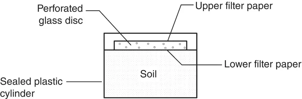
Fig. 2.17 Soil suction measurement – an arrangement for the filter paper method.
The tensiometer
Stannard (1992) presented a review of the standard tensiometer and covered the relevant theory, its construction, and possible uses. The apparatus is mainly used for in situ measurements and consists of a porous ceramic cup placed in contact with the soil to be tested.
A borehole is put down to the required depth and the ceramic filter lowered into position. Water is then allowed to exit from a water reservoir within the tensiometer and to enter the soil. The operation continues until the tensile stress holding the water in the tensiometer equals the stress holding the water in the soil (i.e. the total soil suction).
The tensile stress in the water in the tensiometer is measured by a pressure measuring transducer and is taken to be the value of the total soil suction.
The tensiometer must be fully de‐aired during installation if accurate results are to be obtained. The response time of the type of apparatus described is only a few minutes but it has the disadvantage, until recently, that it could only be used to measure suctions up to about 100 kPa.
2.14 Earth dams
2.14.1 Seepage patterns through an earth dam
As the upper flow line is subjected to atmospheric pressure, the boundary conditions are not completely defined, and it is consequently difficult to sketch a flow net until this line has been located.
Part of such a flow net is shown in Fig. 2.18. It has already been shown that the hydraulic head at a point is the summation of velocity, pressure, and elevation heads. As the top flow line is at atmospheric pressure, the only type of head that can exist along it is elevational, so that between each successive point where an equipotential cuts an upper flow line, there must be equal drops in elevation. This is the first of three conditions that must be satisfied by the upper flow line.
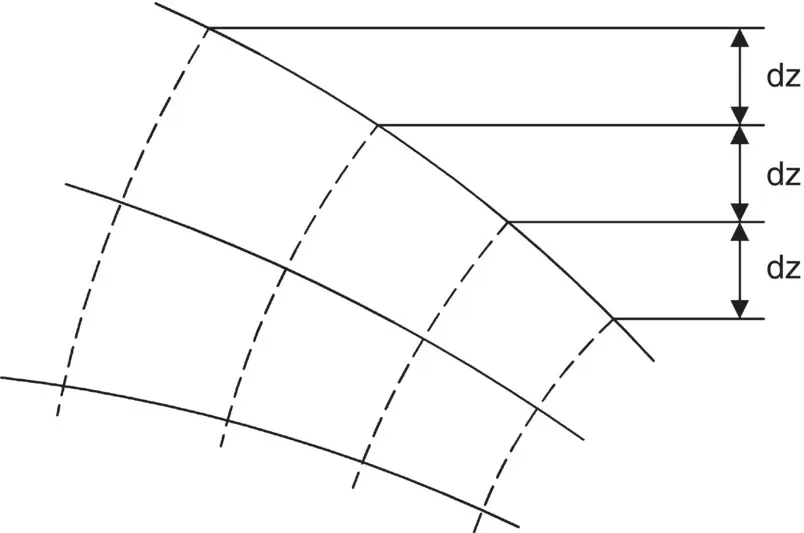
Fig. 2.18 Part of a flow net for an earth dam.
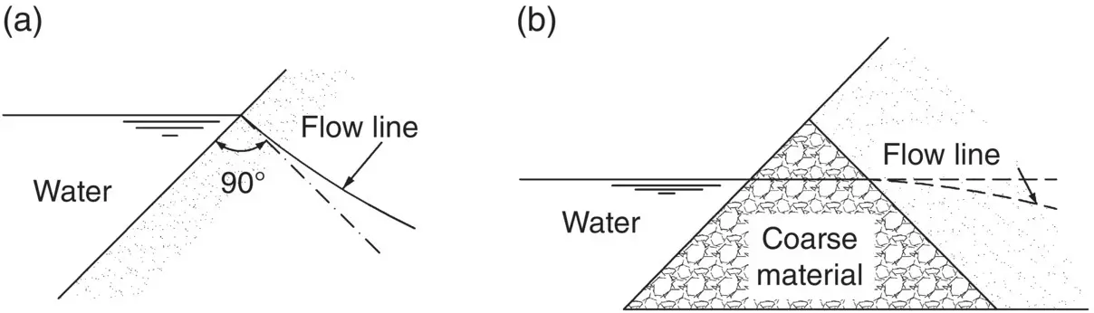
Fig. 2.19 Conditions at the start of an upper flow line.
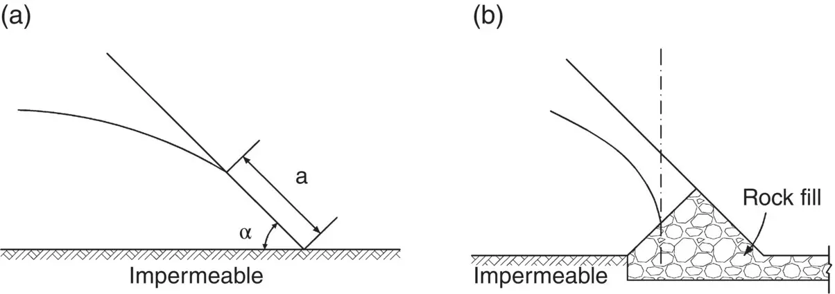
Fig. 2.20 Conditions at the downstream end of an upper flow line. (a) Flow line tangential to downstream slope. (b) Flow line vertical at exit.
The second condition is that, as the upstream face of the dam is an equipotential, the flow line must start at right angles to it (see Fig. 2.19a), but an exception to this rule is illustrated in Fig. 2.19b where the coarse material is so permeable that the resistance to flow is negligible and the upstream equipotential is, in effect, the downstream face of the coarse material. The top flow line cannot be normal to this surface as water with elevation head only cannot flow upwards, so that in this case the flow line starts horizontally.
The third condition concerns the downstream end of the flow line where the water tends to follow the direction of gravity and the flow line either exits at a tangent to the downstream face of the dam ( Fig. 2.20a) or, if a filter of coarse material is inserted, takes up a vertical direction in its exit into the filter ( Fig. 2.20b).
2.14.2 Types of flow occurring in an earth dam
From Fig. 2.20, it is seen that an earth dam may be subjected to two types of seepage: when the dam rests on an impermeable base, the discharge must occur on the surface of the downstream slope (the upper flow line for this case is shown in Fig. 2.21a), whereas when the dam sits on a base that is permeable at its downstream end, the discharge will occur within the dam ( Fig. 2.21b). This is known as the underdrainage case . From a stability point of view, underdrainage is more satisfactory since there is less chance of erosion at the downstream face and the slope can therefore be steeper but, on the other hand, seepage loss is smaller in dams resting on impermeable bases.
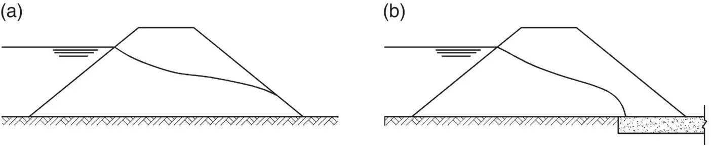
Fig. 2.21 Types of seepage through an earth dam. (a) Impermeable base. (b) Base permeable at down‐stream end.
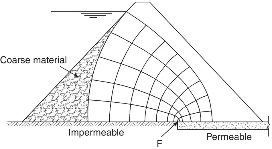
Fig. 2.22 Flow net for a theoretical earth dam.
2.14.3 Parabolic solutions for seepage through an earth dam
In Fig. 2.22is shown the cross‐section of a theoretical earth dam, the flow net of which consists of two sets of parabolas. The flow lines all have the same focus, F, as do the equipotential lines. Apart from the upstream end, actual dams do not differ substantially from this imaginary example, so that the flow net for the middle and downstream portions of the dam are similar to the theoretical parabolas (a parabola is a curve, such that any point along it is equidistant from both a fixed point, called the focus, and a fixed straight line, called the directrix). In Fig. 2.23, FC = CB.
The graphical method for determining the phreatic surface in an earth dam was evolved by Casagrande (1937) and involves the drawing of an actual parabola and then the correction of the upstream end. Casagrande showed that this parabola should start at the point C of Fig. 2.24(which depicts a cross‐section of a typical earth dam) where AC ≈ 0.3AB (the focus, F, is the upstream edge of the filter). To determine the directrix, draw, with compasses, the arc of the circle as shown, using centre C and radius CF; the vertical tangent to this arc is the directrix, DE. The parabola passing through C, with focus F and directrix DE, can now be constructed. Two points that are easy to establish are G and H, as FG = GD and FH = FD; other points can quickly be obtained using compasses. Having completed the parabola, a correction is made as shown to its upstream end so that the flow line actually starts from A.
Читать дальшеИнтервал:
Закладка:
Похожие книги на «Smith's Elements of Soil Mechanics»
Представляем Вашему вниманию похожие книги на «Smith's Elements of Soil Mechanics» списком для выбора. Мы отобрали схожую по названию и смыслу литературу в надежде предоставить читателям больше вариантов отыскать новые, интересные, ещё непрочитанные произведения.


Обсуждение, отзывы о книге «Smith's Elements of Soil Mechanics» и просто собственные мнения читателей. Оставьте ваши комментарии, напишите, что Вы думаете о произведении, его смысле или главных героях. Укажите что конкретно понравилось, а что нет, и почему Вы так считаете.