Joseph R. Badick - Flight Theory and Aerodynamics
Здесь есть возможность читать онлайн «Joseph R. Badick - Flight Theory and Aerodynamics» — ознакомительный отрывок электронной книги совершенно бесплатно, а после прочтения отрывка купить полную версию. В некоторых случаях можно слушать аудио, скачать через торрент в формате fb2 и присутствует краткое содержание. Жанр: unrecognised, на английском языке. Описание произведения, (предисловие) а так же отзывы посетителей доступны на портале библиотеки ЛибКат.
- Название:Flight Theory and Aerodynamics
- Автор:
- Жанр:
- Год:неизвестен
- ISBN:нет данных
- Рейтинг книги:4 / 5. Голосов: 1
-
Избранное:Добавить в избранное
- Отзывы:
-
Ваша оценка:
Flight Theory and Aerodynamics: краткое содержание, описание и аннотация
Предлагаем к чтению аннотацию, описание, краткое содержание или предисловие (зависит от того, что написал сам автор книги «Flight Theory and Aerodynamics»). Если вы не нашли необходимую информацию о книге — напишите в комментариях, мы постараемся отыскать её.
AERODYNAMICS
GET A PILOT’S PERSPECTIVE ON FLIGHT AERODYNAMICS FROM THE MOST UP-TO-DATE EDITION OF A CLASSIC TEXT Flight Theory and Aerodynamics
Flight Theory and Aerodynamics
Flight Theory and Aerodynamics
Flight Theory and Aerodynamics — читать онлайн ознакомительный отрывок
Ниже представлен текст книги, разбитый по страницам. Система сохранения места последней прочитанной страницы, позволяет с удобством читать онлайн бесплатно книгу «Flight Theory and Aerodynamics», без необходимости каждый раз заново искать на чём Вы остановились. Поставьте закладку, и сможете в любой момент перейти на страницу, на которой закончили чтение.
Интервал:
Закладка:
3 Mean camber line is a line drawn equidistant between the upper surface and the lower surfaces.
4 Maximum camber is the maximum distance between the mean camber line and the chord line. The location of maximum camber is important in determining the aerodynamic characteristics of the airfoil.
5 Maximum thickness is the maximum distance between the upper and lower surfaces, and its location of maximum thickness will also be important when determining aerodynamic characteristics.
6 Leading edge radius is a measure of the sharpness of the leading edge. It may vary from zero for a knife‐edge supersonic airfoil to about 2% (of the chord) for rather blunt leading edge airfoils.
Definitions
Flight path velocity: The speed and direction of a body passing through the air.
Relative wind (RW): The speed and direction of the air impinging on a body passing through it. It is equal and opposite in direction to the flight path velocity.
Angle of attack (AOA or α, pronounced alpha): The acute angle between the relative wind and the chord line of an airfoil.
Aerodynamic force (AF): The net resulting static pressure multiplied by the planform area of an airfoil.
Lift: The component L of the aerodynamic force that is perpendicular to the relative wind.
Drag: The component D of the aerodynamic force that is parallel to the relative wind.
Center of pressure (CP): The point on the chord line where the aerodynamic force acts.
Laminar flow or streamlined flow: Smooth airflow with little transfer of momentum between parallel layers.
Turbulent flow: Airflow where the streamlines break up and there is much mixing of the layers.
Geometry Variables of Airfoils
There are four main variables in the geometry of an airfoil:
1 Shape of the mean camber line
2 Thickness
3 Location of maximum thickness
4 Leading edge radius
In a cambered airfoil (nonsymmetrical), the mean camber line and chord line are different. If the mean camber line coincides with the chord line, the airfoil is said to be symmetrical. Figure 3.15shows the difference between a cambered and symmetrical airfoil, note the position of the chord line. In symmetrical airfoils, the upper and lower surfaces have the same shape and are equidistant from the chord line. Symmetrical airfoils are common in rotary‐wing blades and in some aerobatic aircraft. Figure 3.16shows examples of early airfoil design to more modern, supersonic designs.
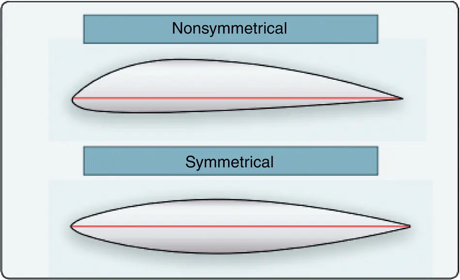
Figure 3.15 Cambered versus symmetrical airfoil.
Source: U.S. Department of Transportation Federal Aviation Administration (2019).
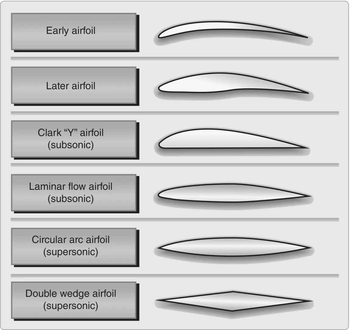
Figure 3.16 Examples of airfoil design.
Source: U.S. Department of Transportation Federal Aviation Administration (2008a).
Classification of Airfoils
Most airfoil development in the United States was done by the National Advisory Committee for Aeronautics (NACA) starting in 1929. NACA was the forerunner of the National Aeronautics and Space Administration (NASA). The first series of airfoils investigated was the “four‐digit” series. The first digit gives the amount of camber, in percentage of chord. The second digit gives the position of maximum camber, in tenths of chord, and the last two give the maximum thickness, in percentage of chord. For example, a NACA 2415 airfoil has a maximum camber of 2% C, located at 40% C (measured from the leading edge), and has a maximum thickness of 15% C. A NACA 0012 airfoil is a symmetrical airfoil (has zero camber) and has a thickness of 12% C.
Further development led to the “five‐digit” series, the “1‐series,” and, with the advent of higher speeds, to the so‐called laminar flow airfoils. The NACA’s 23000 series created in 1935 were very popular and are still in use today. The laminar flow airfoils are the “6‐series” and “7‐series” airfoils and result from moving the maximum thickness back and reducing the leading edge radius.
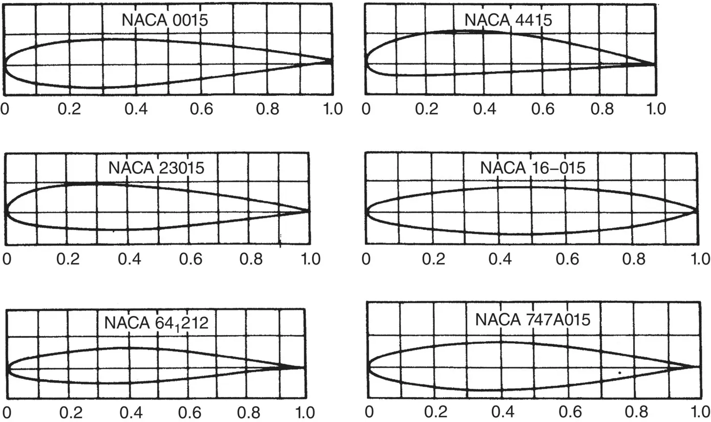
Figure 3.17 NACA airfoils (NACA data).
Two things happen with this treatment. First, the point of minimum pressure is moved backward, thus increasing the distance from the leading edge that laminar (smooth) airflow exists, which reduces drag. Second, the critical Mach number is increased, thus allowing the airspeed of the aircraft to be increased without encountering compressibility problems. In the 6‐series, the first digit indicates the series and the second gives the location of minimum pressure in tenths of chord. The third digit represents the design lift coefficient in tenths, and the last two digits (as in all NACA airfoils) show the thickness in percentage of chord. For example, NACA 64‐212 is a 6‐series airfoil with minimum pressure at 40% C, a design lift coefficient of 0.2, and a thickness of 12% C. Sketches of NACA subsonic airfoil series are shown in Figure 3.17. National Aeronautics and Space Administration’s (NASA) FoilSim interactive simulation software developed by the Glenn Research Center comprises an excellent tool to explore the various shapes of airfoils and how air flows around them when airfoil characteristics are manipulated.
A modern design used worldwide on corporate, military, and air transport aircraft is the supercritical airfoil , which is flatter on top and more rounded on the bottom than a conventional wing. The upper trailing edge has a downward curve to restore lift lost by the flattening of the upper surface. The benefit of this design in the high‐speed realm of flight, as well as other supersonic airfoils, is discussed in Chapter 14.
Application 3.1
Symmetrical airfoils are found on many different types of aircraft, from light to heavy aircraft, and within general aviation to those designed solely for military operations.
Identify various aircraft that incorporate symmetrical airfoils into their design. Where are these airfoils located on the aircraft, and why was the symmetrical airfoil design utilized instead of a cambered airfoil design?
Development of Forces on Airfoils
Leonardo da Vinci stated the cardinal principle of wind tunnel testing nearly 400 years before the Wright brothers achieved powered flight. Near the beginning of the sixteenth century, da Vinci said: the action of the medium upon a body is the same whether the body moves in a quiescent medium, or whether the particles of the medium impinge with the same velocity upon the quiescent body . This principle allows us to consider only relative motion of the airfoil and the air surrounding it. We may use such terms as “airfoil passing through the air” and “air passing over the airfoil” interchangeably.
Pressure Disturbances on Airfoils
If an airfoil is subjected to a moving airflow, velocity and pressure changes take place that create pressure disturbances in the airflow surrounding it. These disturbances originate at the airfoil surface and propagate in all directions at the speed of sound. If the flight path velocity is subsonic, the pressure disturbances that are moving ahead of the airfoil affect the airflow approaching the airfoil ( Figure 3.18). As the arrow indicates there are slight changes with the streamlines ahead of the leading edge of the airfoil.
Читать дальшеИнтервал:
Закладка:
Похожие книги на «Flight Theory and Aerodynamics»
Представляем Вашему вниманию похожие книги на «Flight Theory and Aerodynamics» списком для выбора. Мы отобрали схожую по названию и смыслу литературу в надежде предоставить читателям больше вариантов отыскать новые, интересные, ещё непрочитанные произведения.


Обсуждение, отзывы о книге «Flight Theory and Aerodynamics» и просто собственные мнения читателей. Оставьте ваши комментарии, напишите, что Вы думаете о произведении, его смысле или главных героях. Укажите что конкретно понравилось, а что нет, и почему Вы так считаете.