Joseph R. Badick - Flight Theory and Aerodynamics
Здесь есть возможность читать онлайн «Joseph R. Badick - Flight Theory and Aerodynamics» — ознакомительный отрывок электронной книги совершенно бесплатно, а после прочтения отрывка купить полную версию. В некоторых случаях можно слушать аудио, скачать через торрент в формате fb2 и присутствует краткое содержание. Жанр: unrecognised, на английском языке. Описание произведения, (предисловие) а так же отзывы посетителей доступны на портале библиотеки ЛибКат.
- Название:Flight Theory and Aerodynamics
- Автор:
- Жанр:
- Год:неизвестен
- ISBN:нет данных
- Рейтинг книги:4 / 5. Голосов: 1
-
Избранное:Добавить в избранное
- Отзывы:
-
Ваша оценка:
Flight Theory and Aerodynamics: краткое содержание, описание и аннотация
Предлагаем к чтению аннотацию, описание, краткое содержание или предисловие (зависит от того, что написал сам автор книги «Flight Theory and Aerodynamics»). Если вы не нашли необходимую информацию о книге — напишите в комментариях, мы постараемся отыскать её.
AERODYNAMICS
GET A PILOT’S PERSPECTIVE ON FLIGHT AERODYNAMICS FROM THE MOST UP-TO-DATE EDITION OF A CLASSIC TEXT Flight Theory and Aerodynamics
Flight Theory and Aerodynamics
Flight Theory and Aerodynamics
Flight Theory and Aerodynamics — читать онлайн ознакомительный отрывок
Ниже представлен текст книги, разбитый по страницам. Система сохранения места последней прочитанной страницы, позволяет с удобством читать онлайн бесплатно книгу «Flight Theory and Aerodynamics», без необходимости каждый раз заново искать на чём Вы остановились. Поставьте закладку, и сможете в любой момент перейти на страницу, на которой закончили чтение.
Интервал:
Закладка:
The ailerons are usually located on the trailing edge of each wing closer to the outboard area by the tip. Ailerons control roll about the longitudinal axis as they move opposite of each other when the pilot banks left or right with the yoke or stick, with the “up” aileron on the downward moving wing. Most ailerons are connected by a mechanical means to the aircraft yoke through cables, bell cranks, pulleys, and/or push‐pull tubes. Some jet aircraft have additional ailerons located in the midwing area for high‐speed maneuvering, to reduce roll rate.
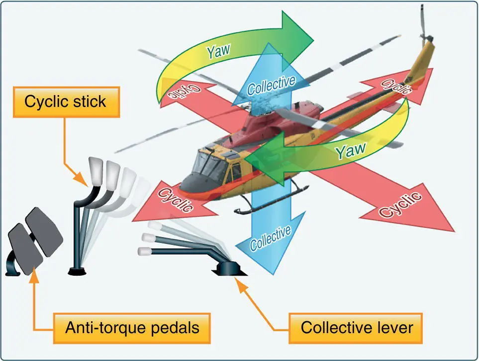
Figure 3.2 Helicopter flight controls.
Source: U.S. Department of Transportation Federal Aviation Administration (2016b).
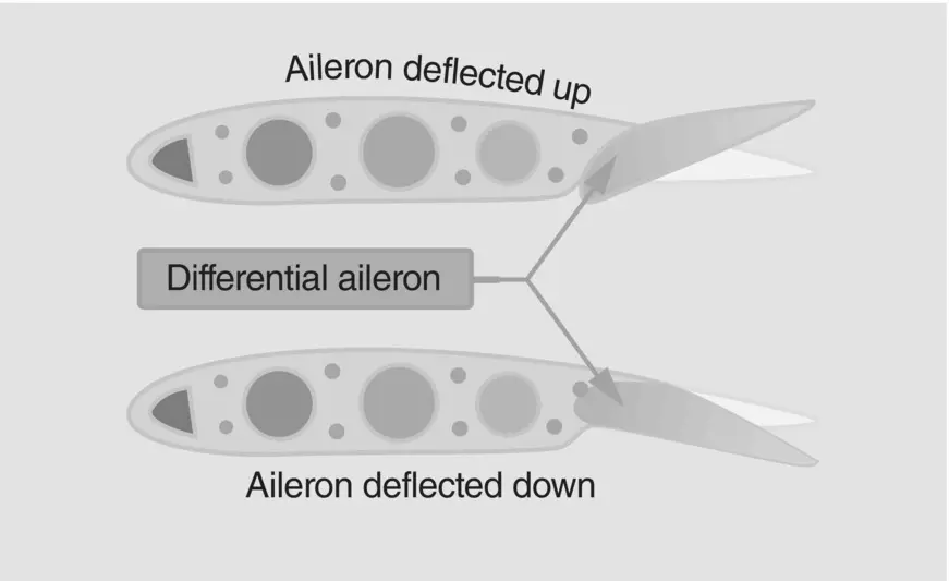
Figure 3.3 Differential ailerons.
Source: U.S. Department of Transportation Federal Aviation Administration (2008a).
When the yoke/stick is moved to the left, the ailerons deflect in opposite directions, the aileron on the left wing rises and the aileron on the right wing deflects downward. This action results in more lift on the right wing and a resultant roll to the left around the longitudinal axis. Later in Section 3.3of Chapter 4we will explain why this happens.
There are many styles of ailerons used throughout the fixed‐wing aircraft industry today, including differential ailerons, frise‐type ailerons, and flaperons. Differential ailerons work by deflecting the up aileron more than the down aileron, increasing drag on the downward wing counteracting adverse yaw ( Figure 3.3). Frise‐type ailerons project the leading edge of the raised aileron into the wind, increasing drag on the lowered wing to once again minimize the effects of adverse yaw ( Figure 3.4). Flaperons combine the control surfaces of the ailerons with the function of the trailing edge flaps, as they can be lowered like flaps but still control bank angle like traditional ailerons. Chapters 12and 13in this textbook will discuss these items, as well as adverse yaw, in more depth regarding aircraft stability.
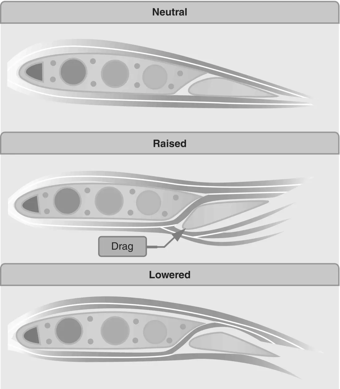
Figure 3.4 Frise‐type ailerons.
Source: U.S. Department of Transportation Federal Aviation Administration (2008a).
Elevator/Stabilator
An elevator or stabilator controls pitch about the lateral axis, allowing for varying angles of attack during flight. An elevator is attached to the trailing edge of the horizontal stabilizer, which is usually fixed to the empennage, sometimes with an angle of incidence built in. A stabilator is a one‐piece horizontal stabilizer which moves as a unit around a pivot point in order to allow the pilot to control the angle of attack by adjusting the tail‐down force resulting in pitch variations of the nose of the aircraft.
The elevator is controlled by the pilot through various mechanical linkages; when the pilot pulls aft on the stick, the elevator forces the tail down, so the nose pitches up, and when the pilot pushes forward the elevator forces the tail up, so the nose goes down. As discussed in Chapter 2, the tail‐down force provides a moment that moves the nose of the aircraft around the aircraft’s center of gravity. In the example of an up elevator, when the pilot pulls aft on the stick, a larger “camber” is created on the tail and thus a greater aerodynamic force is created ( Figure 3.5).
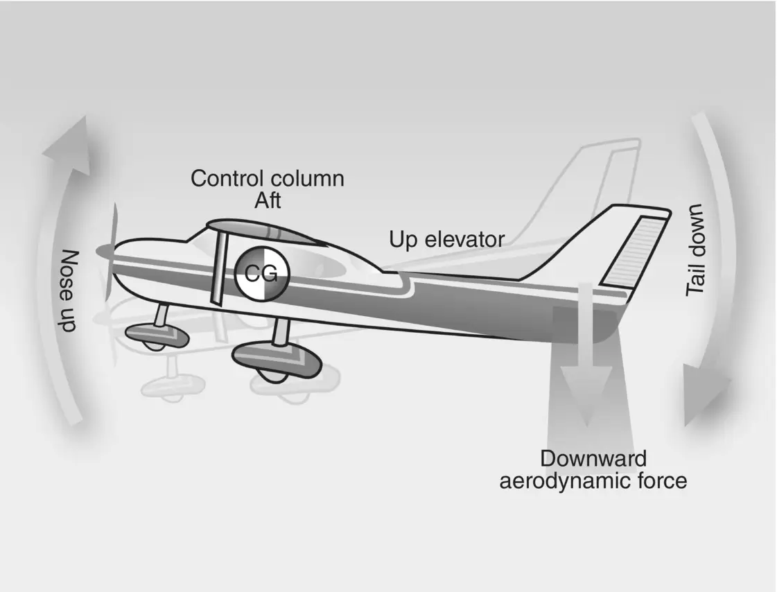
Figure 3.5 Elevator movement.
Source : U.S. Department of Transportation Federal Aviation Administration (2008a).
A stabilator essentially works like the elevator, but due to the fact the entire rear horizontal piece is movable, more force is created when the pilot moves the stick fore and aft and sensitivity is increased. This leads to greater chances of the pilot overcontrolling the aircraft; so, components like an antiservo tab and balance weight are added to reduce the sensitivity.
Some larger aircraft incorporate an adjustable horizontal stabilizer controlled by a jackscrew through a wheel in the cockpit or a motor. Though an elevator is still located on the trailing edge, the usually fixed horizontal stabilizer is adjustable, in this case allowing the pilot to move the stabilizer to reduce control pressures on the stick ( Figure 3.6).
Rudder
The rudder controls yaw, or movement of the aircraft about its vertical axis. Similar to the smaller, movable elevator attached to the trailing edge of the horizontal stabilizer, the rudder is attached to the rear of the fixed vertical stabilizer. As with other components we discussed, the rudder is connected to the rudder pedals in the cockpit via various mechanical linkages; pressing on the left or right rudder pedal moves the rudder left or right, respectively. Most of the time, the rudder is used to maintain coordinated flight, especially when banking the aircraft. Moving the rudder creates a larger camber on the vertical stabilizer, which in turn creates a greater sideways force. This force causes the nose of the aircraft to move left and right, or yaw, around the vertical axis ( Figure 3.7).
Canard
The canard design dates back to the glider designs of the Wright Flyer, and can still be found on a few modern civilian and military aircraft. Though few were made, the Beechcraft Starship is a great example of an aircraft with a canard design. Most canard designs incorporate a horizontal stabilizer in front of the main wings, providing lift for the nose instead of the previously presented aft horizontal stabilizer which provides tail‐down force.
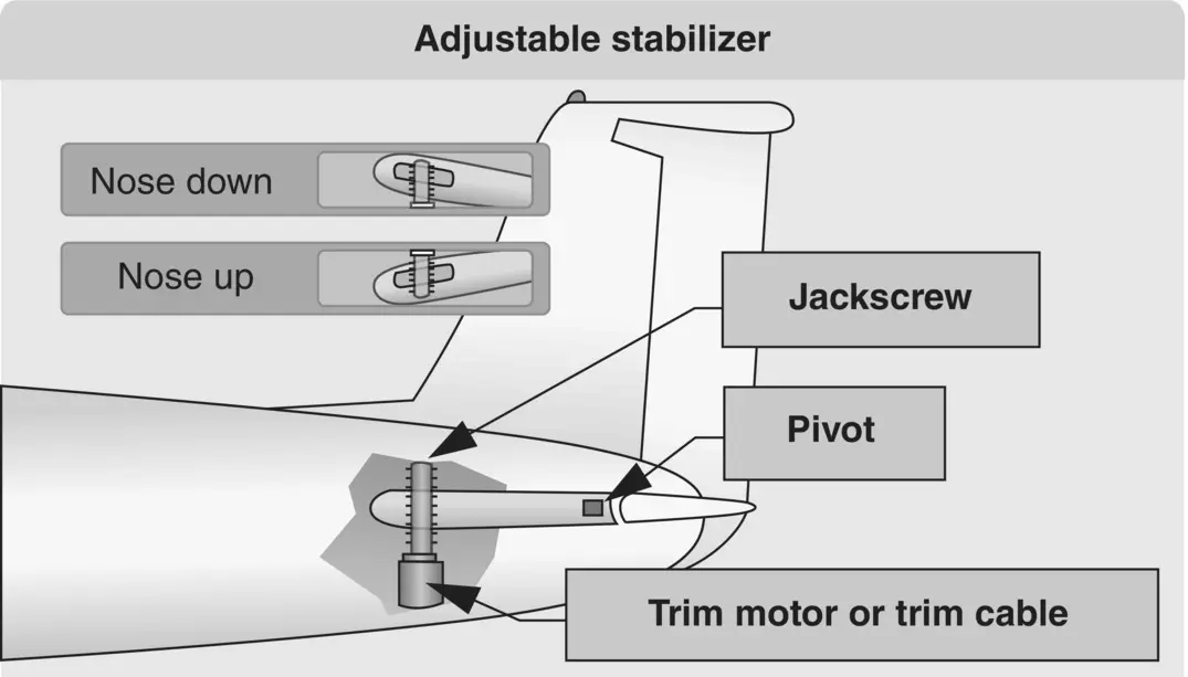
Figure 3.6 Adjustable horizontal stabilizer.
Source: U.S. Department of Transportation Federal Aviation Administration (2008a).
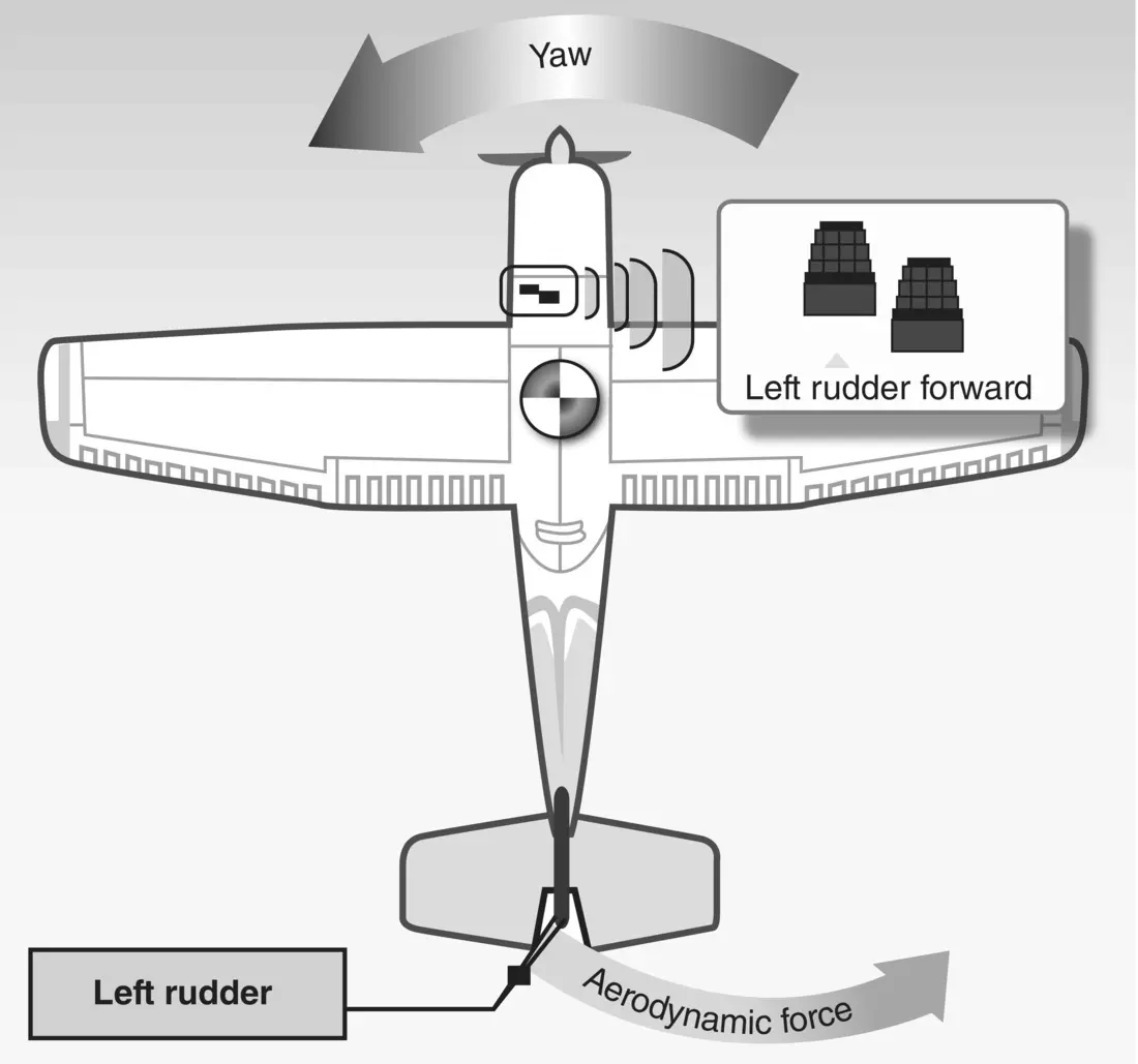
Figure 3.7 Rudder movement.
Source: U.S. Department of Transportation Federal Aviation Administration (2008a).
Secondary Flight Controls
Secondary flight control systems usually consist of wing flaps, leading edge devices, spoilers, and trim systems. These controls often support or supplement the primary controls, and their importance to understanding aerodynamic principles cannot be overstated.
Flaps
The flaps are the most common high‐lift devices used on aircraft, and their contribution to the amount of lift an airfoil can produce will be discussed in more detail in Chapter 4. For our discussion here, we will review their location on the aircraft, as well as the basic flap designs on aircraft today.
Flaps for this discussion are considered to be on the trailing edge of the wing, usually inboard close to the fuselage, and are referred to as trailing edge flaps. These surfaces contribute to the camber of the wing airfoil in most cases, as well as to the area of the wing in other cases. By increasing the angle of attack of the wing, and in some cases the area of the wing, they allow the aircraft to fly at lower speeds, which may be needed for takeoff and landing, or for situations requiring increased maneuverability. Flaps increase the lift as well as the drag, and it is generally considered that 15° or less of flaps produce more lift than drag, and any flap setting over 15° drag exceeds lift. For this discussion, we will look at four types of flaps: plain, split, slotted, and Fowler; and as you can see, there are designs where the benefit of one design is combined with another ( Figure 3.8).
Читать дальшеИнтервал:
Закладка:
Похожие книги на «Flight Theory and Aerodynamics»
Представляем Вашему вниманию похожие книги на «Flight Theory and Aerodynamics» списком для выбора. Мы отобрали схожую по названию и смыслу литературу в надежде предоставить читателям больше вариантов отыскать новые, интересные, ещё непрочитанные произведения.


Обсуждение, отзывы о книге «Flight Theory and Aerodynamics» и просто собственные мнения читателей. Оставьте ваши комментарии, напишите, что Вы думаете о произведении, его смысле или главных героях. Укажите что конкретно понравилось, а что нет, и почему Вы так считаете.