Joseph R. Badick - Flight Theory and Aerodynamics
Здесь есть возможность читать онлайн «Joseph R. Badick - Flight Theory and Aerodynamics» — ознакомительный отрывок электронной книги совершенно бесплатно, а после прочтения отрывка купить полную версию. В некоторых случаях можно слушать аудио, скачать через торрент в формате fb2 и присутствует краткое содержание. Жанр: unrecognised, на английском языке. Описание произведения, (предисловие) а так же отзывы посетителей доступны на портале библиотеки ЛибКат.
- Название:Flight Theory and Aerodynamics
- Автор:
- Жанр:
- Год:неизвестен
- ISBN:нет данных
- Рейтинг книги:4 / 5. Голосов: 1
-
Избранное:Добавить в избранное
- Отзывы:
-
Ваша оценка:
Flight Theory and Aerodynamics: краткое содержание, описание и аннотация
Предлагаем к чтению аннотацию, описание, краткое содержание или предисловие (зависит от того, что написал сам автор книги «Flight Theory and Aerodynamics»). Если вы не нашли необходимую информацию о книге — напишите в комментариях, мы постараемся отыскать её.
AERODYNAMICS
GET A PILOT’S PERSPECTIVE ON FLIGHT AERODYNAMICS FROM THE MOST UP-TO-DATE EDITION OF A CLASSIC TEXT Flight Theory and Aerodynamics
Flight Theory and Aerodynamics
Flight Theory and Aerodynamics
Flight Theory and Aerodynamics — читать онлайн ознакомительный отрывок
Ниже представлен текст книги, разбитый по страницам. Система сохранения места последней прочитанной страницы, позволяет с удобством читать онлайн бесплатно книгу «Flight Theory and Aerodynamics», без необходимости каждый раз заново искать на чём Вы остановились. Поставьте закладку, и сможете в любой момент перейти на страницу, на которой закончили чтение.
Интервал:
Закладка:
The plain flap is the simplest design, and illustrates the advantages and purpose of flaps. As the flaps are deployed, the camber of the wing increases, and the lift coefficient ( C L) increases accordingly with the angle of attack. The lift coefficient will be discussed at length in Chapter 4. The farther the flaps are deployed, the greater the lift and the resulting drag. A split flap is deployed from underneath the wing, and results in more drag initially than the plain flap due to the disruption of the flow of air around the bottom and top of the wing.
When the flaps are slotted, at high angles of attack high energy air is allowed to move through the slot and energize the air on top of the deployed flap. This allows for an increase in C Lat lower speeds, allowing an aircraft to operate out of shorter landing strips or with obstacles surrounding the airport. The highly energized air also delays boundary layer separation, which lowers the stalling speed, improving performance at slow speeds. More on this topic will be discussed throughout this textbook.
Fowler flaps are commonly found on larger transport category aircraft, as they are heavier than the other flap designs and incorporate more complex systems to operate. Fowler flaps slide out and back from the wing, which offers the benefit of not only increasing the camber of the wing but also of the wing area. Fowler flaps also double as slotted flaps in that they allow higher‐energy air from beneath the wing to flow over the deployed flap area. Cessna high‐wing, single‐engine aircraft are the best example of the use of Fowler flaps on light aircraft.
Leading Edge Devices
Leading edge devices are discussed in more depth in Chapter 4; so, only a brief introduction will be presented here. As with trailing edge flaps, leading edge devices like movable slots, leading edge flaps (Krueger flaps), and leading edge cuffs work to increase the C Lover a wing, allowing the aircraft to fly at slower speeds for takeoff and landing. In some cases, the camber of the wing is also increased, which allows for an increase in the angle of attack and increased performance. As with trailing edge flaps, the first setting results in more lift with little increase in drag, while fully deployed settings usually result in mostly drag with little lift.
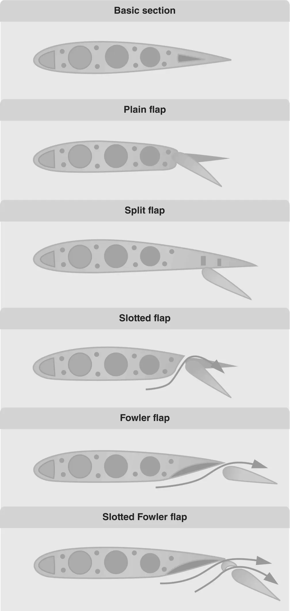
Figure 3.8 Common flap designs.
Source: U.S. Department of Transportation Federal Aviation Administration (2008a).
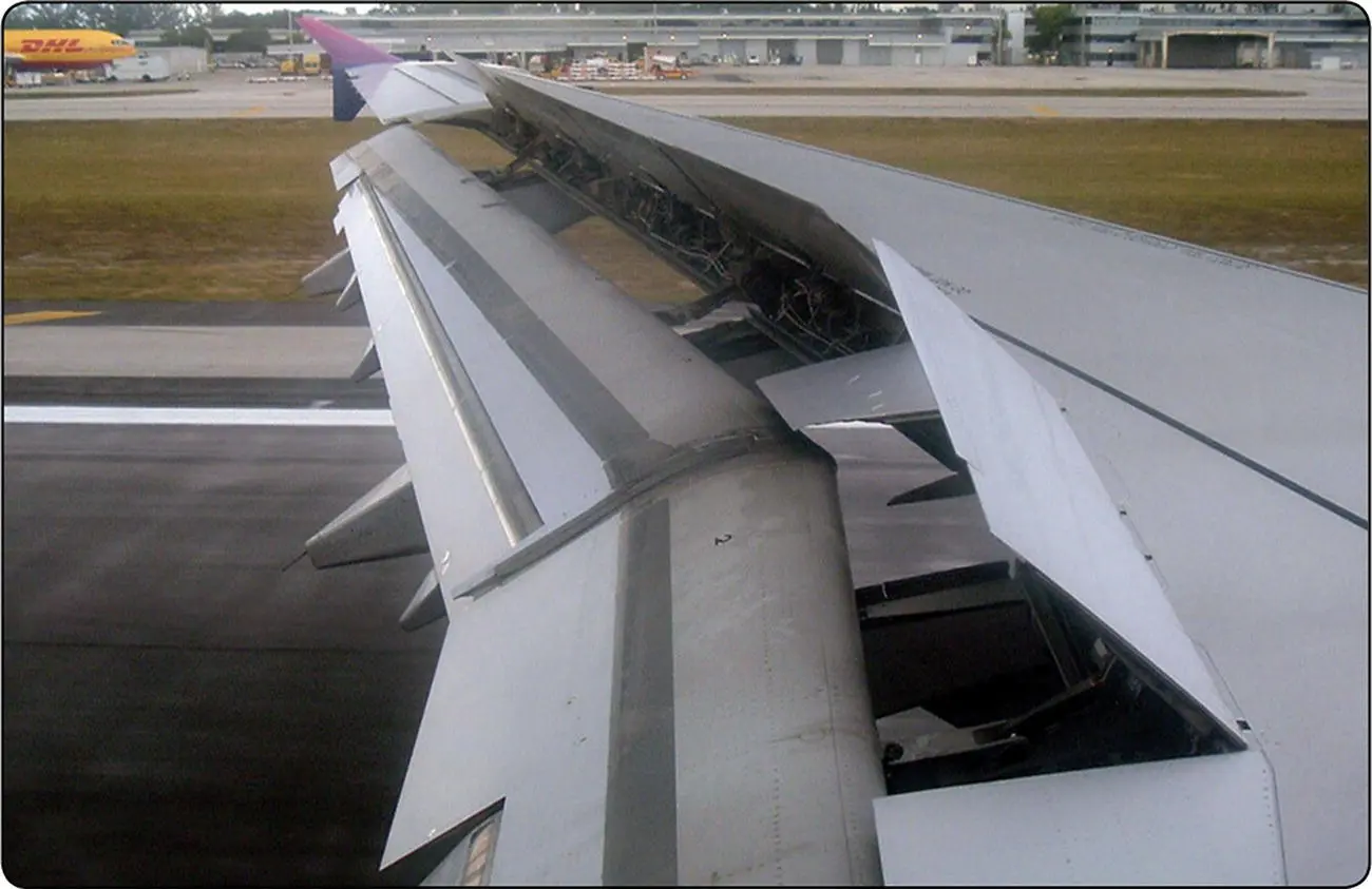
Figure 3.9 Ground spoilers deployed.
Source: U.S. Department of Transportation Federal Aviation Administration (2016b).
Spoilers and Speed Brakes
Spoilers are used on many different types of aircraft as high‐drag devices used to increase drag and reduce lift. They “spoil” the smooth air around a wing, and may be used in flight, or on the ground when landing or during a rejected takeoff. Figure 3.9is an example of deployed ground spoilers to reduce lift over the wing and increase the effectiveness of the brakes. Some aircraft use the spoilers in flight for roll control at higher airspeeds when the action of the ailerons would be too much of a force. Sometimes spoilers are used as speed brakes to reduce lift on both wings, which allows the aircraft to descend without increasing airspeed. Gliders utilize spoilers to control their descent rate upon landing.
Trim Systems and Tabs
Trim systems are designed to alleviate the pressures on the primary flight controls as experienced by the pilot during aircraft operation. Usually located on the trailing edge of these devices, the pilot (or autopilot) operates the respective trim system in order to position the flight control where minimum pressures are exerted in the system. The two most common trim systems are trim tabs and antiservo tabs.
A trim tab is usually found on the trailing edge of the elevator or rudder, and unlike the antiservo tab, the trim tab moves in the opposite direction to which the primary control moves ( Figure 3.10). An antiservo tab is found on the trailing edge of a stabilator, and moves in the same direction as the primary control to which it is attached ( Figure 3.11). As previously mentioned, the antiservo tab serves to reduce the sensitivity of the stabilator during pitch to the pilot, as well as reducing control pressure as needed.
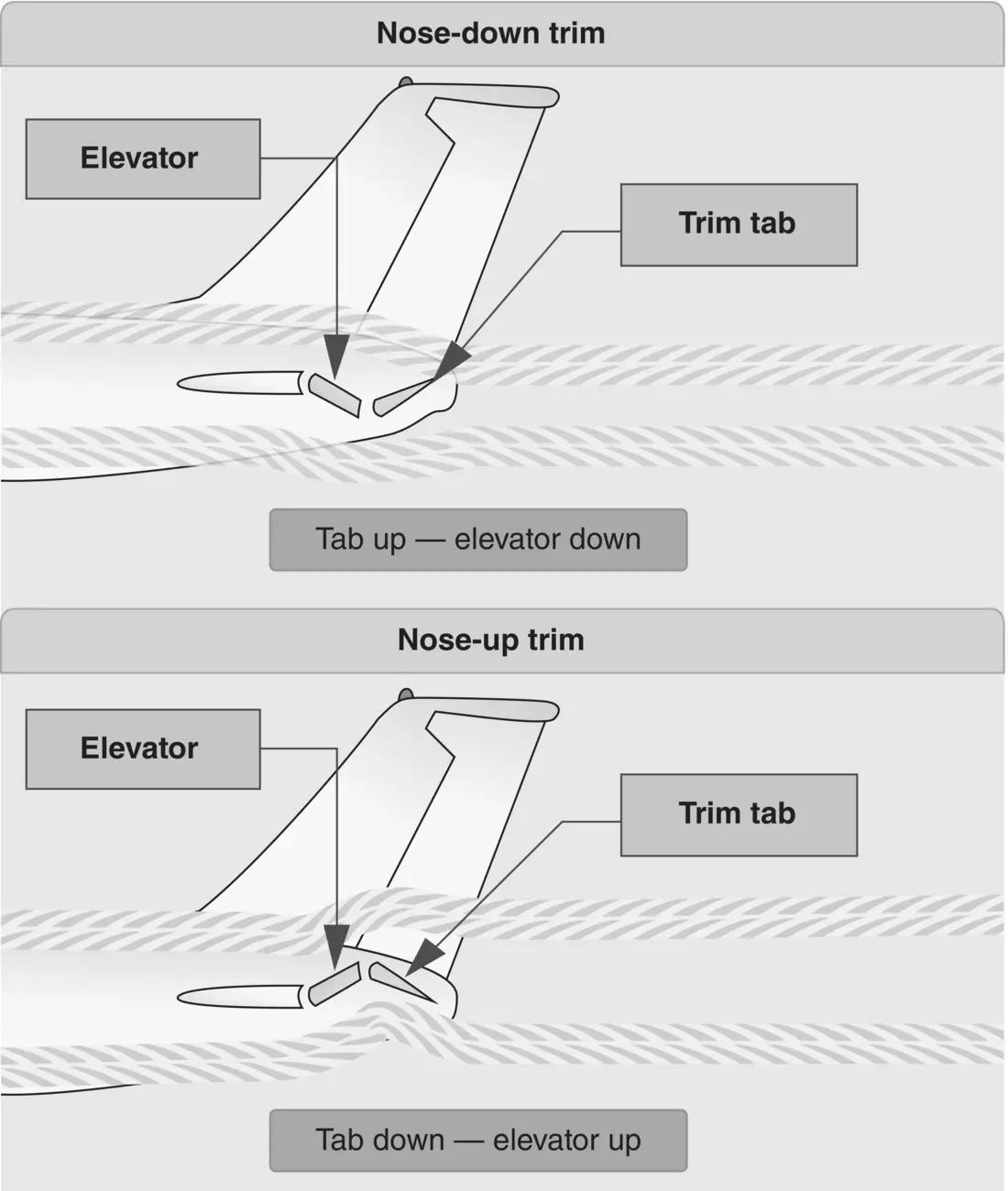
Figure 3.10 Trim tabs.
Source: U.S. Department of Transportation Federal Aviation Administration (2008a).
Some smaller aircraft may incorporate a different type of trim tab that does not involve an independent mechanical linkage, this type of trim tab consists only of a metal plate attached to the trailing edge of a primary flight control. When set correctly, this allows the pilot to fly “hands‐off” the flight control while in straight and level flight. Figure 3.12provides a summary of the many secondary flight controls available, including their location on the aircraft and function.
AIRFOILS
An airfoil or, more properly, an airfoil section, is commonly shown as a vertical slice of a wing (see Figure 3.13). In discussing airfoils in this chapter, the planform (or horizontal plane) of the wing is ignored as it will be discussed in Chapters 4and 5. Keep in mind during this discussion that an airfoil is also found on the vertical stabilizer, horizontal stabilizer, and rotor blades. Wingtip effects, sweepback, taper, wash/out or wash/in, and other design features are not considered. No single airfoil design is perfect for every flight situation: wind tunnel tests, and computer‐generated designs dictate what airfoil is best for the mission of the aircraft.
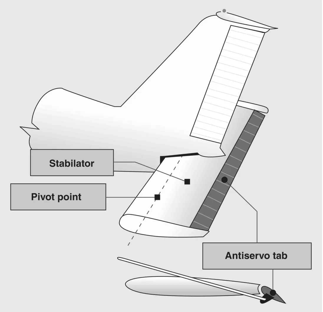
Figure 3.11 Antiservo Tab.
Source: U.S. Department of Transportation Federal Aviation Administration (2008a).
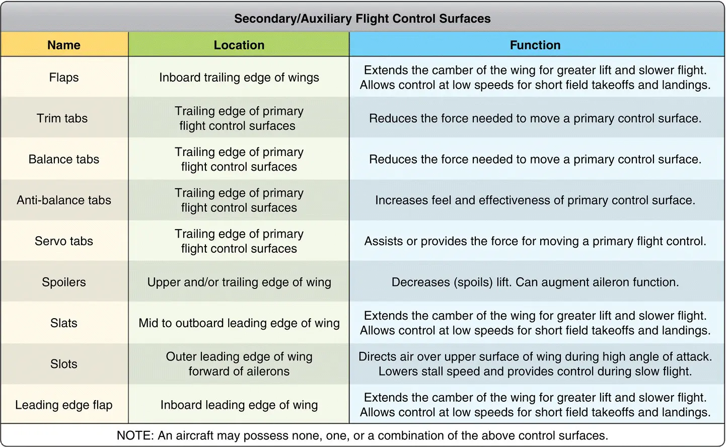
Figure 3.12 Secondary control surfaces and their location.
Source: U.S. Department of Transportation Federal Aviation Administration (2018).
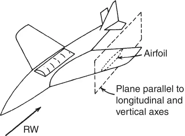
Figure 3.13 Airfoil section.
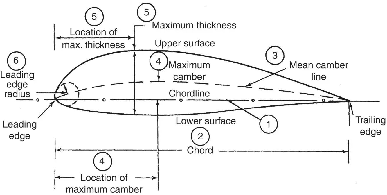
Figure 3.14Airfoil terminology.
Airfoil Terminology
The terminology used to discuss an airfoil is shown in Figure 3.14:
1 Chord line is a straight line connecting the leading edge and the trailing edge of the airfoil.
2 Chord is the length of the chord line. All airfoil dimensions are measured in terms of the chord.
Читать дальшеИнтервал:
Закладка:
Похожие книги на «Flight Theory and Aerodynamics»
Представляем Вашему вниманию похожие книги на «Flight Theory and Aerodynamics» списком для выбора. Мы отобрали схожую по названию и смыслу литературу в надежде предоставить читателям больше вариантов отыскать новые, интересные, ещё непрочитанные произведения.


Обсуждение, отзывы о книге «Flight Theory and Aerodynamics» и просто собственные мнения читателей. Оставьте ваши комментарии, напишите, что Вы думаете о произведении, его смысле или главных героях. Укажите что конкретно понравилось, а что нет, и почему Вы так считаете.