Richard W. Ziolkowski - Advanced Antenna Array Engineering for 6G and Beyond Wireless Communications
Здесь есть возможность читать онлайн «Richard W. Ziolkowski - Advanced Antenna Array Engineering for 6G and Beyond Wireless Communications» — ознакомительный отрывок электронной книги совершенно бесплатно, а после прочтения отрывка купить полную версию. В некоторых случаях можно слушать аудио, скачать через торрент в формате fb2 и присутствует краткое содержание. Жанр: unrecognised, на английском языке. Описание произведения, (предисловие) а так же отзывы посетителей доступны на портале библиотеки ЛибКат.

- Название:Advanced Antenna Array Engineering for 6G and Beyond Wireless Communications
- Автор:
- Жанр:
- Год:неизвестен
- ISBN:нет данных
- Рейтинг книги:3 / 5. Голосов: 1
-
Избранное:Добавить в избранное
- Отзывы:
-
Ваша оценка:
Advanced Antenna Array Engineering for 6G and Beyond Wireless Communications: краткое содержание, описание и аннотация
Предлагаем к чтению аннотацию, описание, краткое содержание или предисловие (зависит от того, что написал сам автор книги «Advanced Antenna Array Engineering for 6G and Beyond Wireless Communications»). Если вы не нашли необходимую информацию о книге — напишите в комментариях, мы постараемся отыскать её.
Reviews advances in the design and deployment of antenna arrays for future generations of wireless communication systems, offering new solutions for the telecommunications industry Advanced Antenna Array Engineering for 6G and Beyond Wireless Communications
Advanced Antenna Array Engineering for 6G and Beyond Wireless Communications
Advanced Antenna Array Engineering for 6G and Beyond Wireless Communications — читать онлайн ознакомительный отрывок
Ниже представлен текст книги, разбитый по страницам. Система сохранения места последней прочитанной страницы, позволяет с удобством читать онлайн бесплатно книгу «Advanced Antenna Array Engineering for 6G and Beyond Wireless Communications», без необходимости каждый раз заново искать на чём Вы остановились. Поставьте закладку, и сможете в любой момент перейти на страницу, на которой закончили чтение.
Интервал:
Закладка:
A high‐level digital beamformer for reception is shown in Figure 1.4. It consists of an array of antennas, each antenna element being connected with an RF receiver. The RF receiver includes a filter, a low noise amplifier, a down converter, and an analog‐to‐digital converter (ADC). Thus, a signal chain is formed for each antenna.
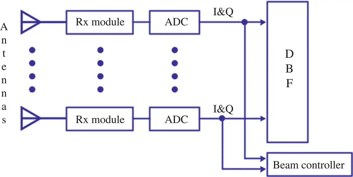
Figure 1.4 High‐level architecture of a digital beamformer (DBP) for reception.
The signals from all of the signal chains are fed into a digital beamformer (DBF). The DBF can form, in principle, as many beams as required. Theoretically it can realize real‐time beamforming via real‐time signal processing. However, in practice, this approach will generally incur prohibitive costs, including computing resources and hardware expenditures in both the RF circuits and digital devices such as ADCs and field‐programmable gate arrays (FPGAs). In fact, the cost of the RF components is almost independent of the desired bandwidth whereas the cost of digital signal processing is approximately proportional to it in terms of both hardware and computing requirements. While those system costs are extensive, the necessary amount of energy to run the system may be even a higher outlay. The energy consumption of a large scale digital beamformer can easily amount to hundreds and even thousands of watts.
These significant practical issues mean that to achieve all of the desired functionalities of future ultra‐high data rate communication systems, fully digital beamforming using massive antenna arrays is simply unaffordable for most application scenarios. Moreover, it is actually not even acceptable for many base station antennas for 5G with the current state of the art of device technologies [9]. These factors lead to the conclusion that some kind of hybrid system based on both digital and analog beamforming might serve as a good solution to large scale antenna arrays with multiple steerable beams in the foreseeable future.
1.3.2 Hybrid Beamforming
Hybrid beamforming is a strategy that combines the advantages of both analog and digital beamforming techniques. The motivation for employing hybrid beamformers is now clear. One wants to reduce hardware costs and processing complexities while retaining nearly the optimal performance that is achievable with optimized digital designs.
The hybrid beamforming approach does not treat every antenna element as a completely independent one. The key concept is to partition a large antenna array into smaller subarrays. This type of array is also known in the 5G literature as an array of subarrays (AOSA) [4]. Each subarray consists of a conventional analog antenna array that forms its beam in the analog domain [12, 13]. The number of sub‐arrays into which the whole array is partitioned determines its degrees of freedom.
When analog beamforming is performed using analog phase shifters and other equivalent devices, significant cost reductions can be achieved immediately due to the decrease in the number of complete RF chains required to form the beams. However, the number of simultaneously supported data streams or beams in a hybrid array is lower in comparison to a full‐blown digital array. In practice, the actual antenna array design depends on the beamforming capabilities required along with the system’s total complexity and budget considerations, both issues being influenced directly by factors such as the number of steerable beams and costs. Although reducing the number of RF chains also limits the number of data streams, per‐user performance can be designed to come close to that attained with a fully digital beamformer. Owing to the nature of line of sight radio propagation and smaller numbers of users per cell, the hybrid beamforming strategy is definitely the more practical beamforming approach for mm‐wave systems in the near future [4, 11].
Figure 1.5a shows the basic architectures of both transmitting and receiving hybrid arrays. Their schematics illustrate the whole array being divided into many analog subarrays [12]. Each subarray includes N antennas and an RF/IF (intermediate frequency) unit. These components can be shared by different antenna elements in different ways, depending on their actual implementations. For convenience, we have simply denoted an array with M subarrays with N antenna elements in each subarray as an N × M hybrid array. Typically, given the dimension of the whole array, the decision on the size of the subarray, or the selection of N and M , is a trade‐off between the system cost and performance. If N is large, a high antenna gain can be achieved at a lower cost. If N is too large, however, the number of users the array can support would be limited. The distance between corresponding elements in adjacent subarrays is called the subarray spacing . It is determined by the desired multiple beam performance and the allowed physical area of the array. Each subarray is connected to a baseband processor via a digital‐to‐analog convertor (DAC) in the transmitter and an analog‐to‐digital convertor (ADC) in the receiver. The signals from all of the subarrays are interconnected and processed centrally in the baseband processor.
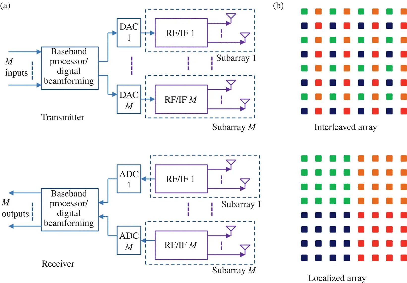
Figure 1.5 Hybrid antenna arrays. (a) The basic architectures of transmitter and receiver systems. (b) Two types of array configurations for uniform square hybrid arrays: interleaved (upper) and localized (bottom). Each square represents an antenna element and squares with the same color represent antenna elements in the same analog subarray.
Source : From [12] / with permission of IEEE.
Signals in the analog subarray and in the digital processor can be processed in different domains and in different ways. A signal in each subarray can be simply weighted in the analog domain mainly for the purpose of achieving array gain and beam steering. The signal for each antenna element in a subarray can be varied in both its magnitude and phase, typically with limited resolution. In the simplest case, only a phase shifter is applied and the signal is weighted by a discrete phase shift value from a quantized set of values. The size of the set is typically represented by the number of quantized bits. For example, a 3‐bit quantization means eight discrete values are uniformly distributed over the angular interval [− π , π ]. In the digital processor, signals from/to all of the subarrays are jointly processed. Advanced techniques which are similar to those utilized in conventional MIMO systems, such as spatial precoding/decoding, can be implemented.
Antenna elements in a hybrid array can be configured in various ways to form different topologies. Each of them has respective advantages and disadvantages. A configuration is typically fixed at the fabrication stage. The typical two types of regular configurations are interleaved and localized arrays. They are illustrated in Figure 1.5b for a 16 × 4 uniform square hybrid array. The antenna elements in each subarray in an interleaved array are distributed uniformly over the whole array. On the other hand, they are adjacent to each other in a localized array.
The analog subarrays in Figure 1.5can be implemented in four different configurations depending on where the phase shifters are placed for beamforming. They are illustrated in Figure 1.6. Figure 1.6a shows the conventional phased array architecture for a receive analog array. Only the phase shifters and antennas are independent; all of the rest of its components are shared by all elements in each analog subarray. This passive power combining architecture incurs losses in the phase shifters and power combiners which increase with the number of antenna elements and operating frequency. These power losses could make large passive arrays impractical. A modification of this architecture is shown in Figure 1.6b. An individual LNA is applied to each antenna element before the phase shifter. This modification reduces the noise significantly and provides increased receiver sensitivity. This architecture can be implemented using either a shared frequency converter (with individual RF chains combined at the input to the mixer) or individual frequency conversion and combining in the IF unit. Figures 1.6c and 1.6d depict more advanced configurations in which the phase shift is implemented in the IF unit and local oscillator (LO) circuits, respectively.
Читать дальшеИнтервал:
Закладка:
Похожие книги на «Advanced Antenna Array Engineering for 6G and Beyond Wireless Communications»
Представляем Вашему вниманию похожие книги на «Advanced Antenna Array Engineering for 6G and Beyond Wireless Communications» списком для выбора. Мы отобрали схожую по названию и смыслу литературу в надежде предоставить читателям больше вариантов отыскать новые, интересные, ещё непрочитанные произведения.


Обсуждение, отзывы о книге «Advanced Antenna Array Engineering for 6G and Beyond Wireless Communications» и просто собственные мнения читателей. Оставьте ваши комментарии, напишите, что Вы думаете о произведении, его смысле или главных героях. Укажите что конкретно понравилось, а что нет, и почему Вы так считаете.