Richard W. Ziolkowski - Advanced Antenna Array Engineering for 6G and Beyond Wireless Communications
Здесь есть возможность читать онлайн «Richard W. Ziolkowski - Advanced Antenna Array Engineering for 6G and Beyond Wireless Communications» — ознакомительный отрывок электронной книги совершенно бесплатно, а после прочтения отрывка купить полную версию. В некоторых случаях можно слушать аудио, скачать через торрент в формате fb2 и присутствует краткое содержание. Жанр: unrecognised, на английском языке. Описание произведения, (предисловие) а так же отзывы посетителей доступны на портале библиотеки ЛибКат.
- Название:Advanced Antenna Array Engineering for 6G and Beyond Wireless Communications
- Автор:
- Жанр:
- Год:неизвестен
- ISBN:нет данных
- Рейтинг книги:3 / 5. Голосов: 1
-
Избранное:Добавить в избранное
- Отзывы:
-
Ваша оценка:
Advanced Antenna Array Engineering for 6G and Beyond Wireless Communications: краткое содержание, описание и аннотация
Предлагаем к чтению аннотацию, описание, краткое содержание или предисловие (зависит от того, что написал сам автор книги «Advanced Antenna Array Engineering for 6G and Beyond Wireless Communications»). Если вы не нашли необходимую информацию о книге — напишите в комментариях, мы постараемся отыскать её.
Reviews advances in the design and deployment of antenna arrays for future generations of wireless communication systems, offering new solutions for the telecommunications industry Advanced Antenna Array Engineering for 6G and Beyond Wireless Communications
Advanced Antenna Array Engineering for 6G and Beyond Wireless Communications
Advanced Antenna Array Engineering for 6G and Beyond Wireless Communications — читать онлайн ознакомительный отрывок
Ниже представлен текст книги, разбитый по страницам. Система сохранения места последней прочитанной страницы, позволяет с удобством читать онлайн бесплатно книгу «Advanced Antenna Array Engineering for 6G and Beyond Wireless Communications», без необходимости каждый раз заново искать на чём Вы остановились. Поставьте закладку, и сможете в любой момент перейти на страницу, на которой закончили чтение.
Интервал:
Закладка:
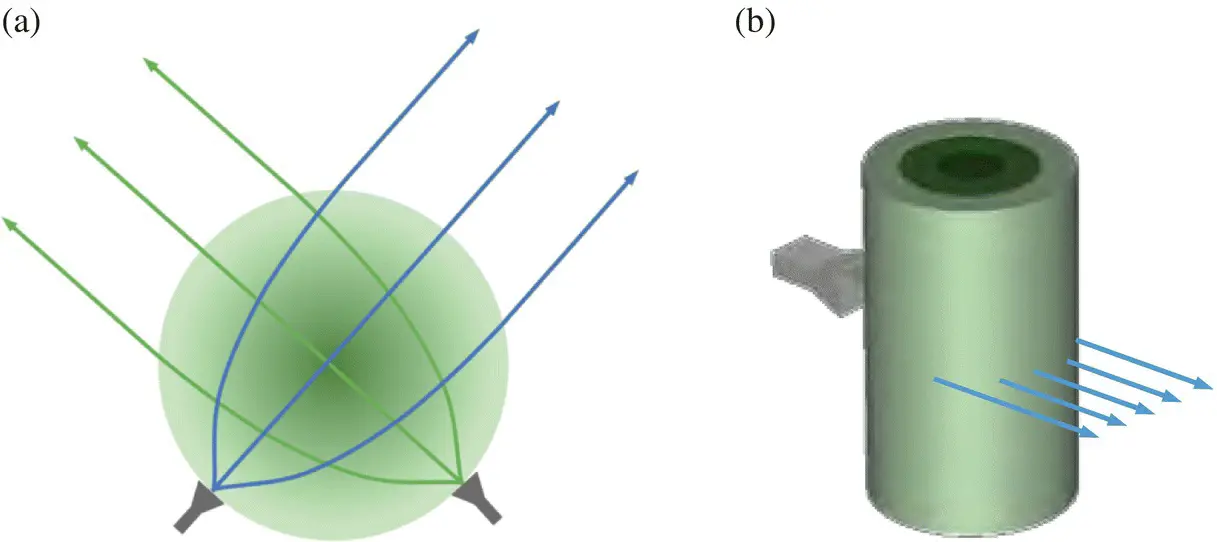
Figure 1.8 Illustration of Luneburg lenses. (a) Spherical. (b) Cylindrical.
The beamwidth of a Luneburg lens is approximately the same as that of a linear array whose length equals the diameter of the lens. Nevertheless, the nulls are considerably deeper. If one places a number of feeds along the surface of a Luneburg lens, one can produce a multiple beam antenna, one beam per feed. These multi‐beam antennas can be employed for data distribution or broadcasting in 5G networks.
It is very difficult and very costly to produce an ideal Luneburg lens. As a practical alternative, one can employ several separate shells to replace the theoretical continuous gradation of the dielectric constant with a discrete approximation to it. Many such versions have been deployed in a variety of current systems.
The main advantages of Luneburg lenses over antenna arrays based on beamforming networks can be summarized as follows [14]:
A great simplification in component count and inherent low passive intermodulation (PIM).
Reduction of network losses.
Beam crossover levels can be selected arbitrarily by choosing the spacing of the source elements.
Isolation between elements is generally superior to that obtained with beamforming networks.
The relative disadvantage of a Luneburg lens antenna is its three‐dimensional bulk compared with planar forms of the array antennas. Nevertheless, some mobile operators are currently showing strong interest in Luneburg lenses due to their low cost in hardware and low energy consumption.
1.5 Millimeter‐Wave Antennas
To date, every new generation of mobile wireless communication has been allocated its own dedicated spectrum. This is again true for 5G networks. Given the fact that the radio spectrum is a worldwide limited resource, the mobile wireless communication industry has been “forced” to start using the mm‐wave spectrum to accommodate some portion of its 5G networks, known as 5G mm‐wave. Application examples include small cells for data‐hungry hot spots and fixed wireless access services where line of sight (LoS) propagation is easier to be guaranteed. Moving forward to 6G, it is expected that some airborne and satellite systems will also embrace the mm‐wave spectrum. Compared with the microwave frequency bands, the propagation of mm‐waves is negatively impacted by higher attenuation rates and severe weather.
To emphasize this issue, Figure 1.9shows the attenuation of electromagnetic waves from DC into the low terahertz (THz) range as functions of the propagation distance, altitude, and weather conditions. Notice that there are some windows in these spectra where the atmospheric attenuation is high, such as around 60 GHz, and, conversely, much lower. The former are clearly not suitable for long‐distance communication. The latter are targeted for many applications. Also notice that the propagation losses are reduced at higher altitudes where the air is thinner. Examining Figure 1.9more closely, it is little wonder that the current “first choice” for commercial 5G rollouts of mm‐wave systems is at the lower end of the mm‐wave range, i.e., around 28 GHz.
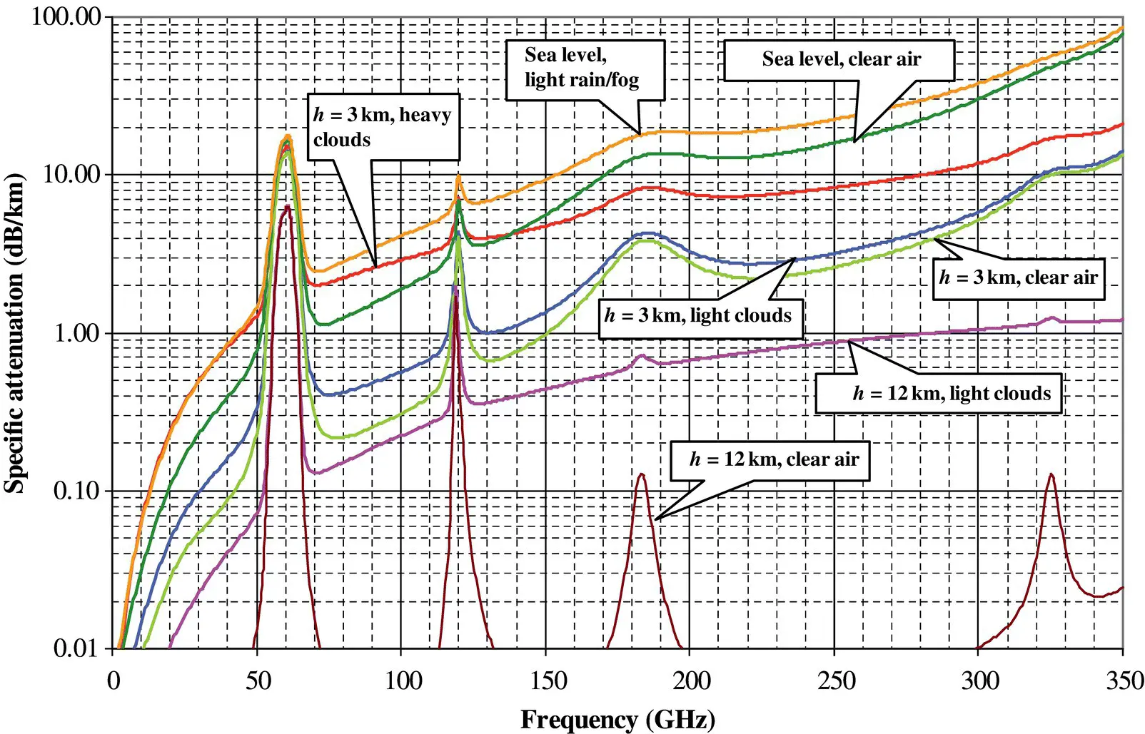
Figure 1.9 Specific atmospheric attenuation (dB/km) at the indicated altitude h and for several exemplary weather and air conditions.
Source : Based on [16] / IEEE.
Certain important advantages for 5G operations are offered by mm‐wave systems. One is that high‐gain mm‐wave antenna arrays can be realized over physically small areas because the associated wavelengths are small (recall that the gain of an aperture antenna – Gain = 4 π Area/ λ 2). In fact, given the inherent high propagation losses of their radiated fields, high‐gain antennas are needed for virtually all mm‐wave communication systems. As a result, it has become imperative to develop mm‐wave beamforming networks to support multi‐beam mm‐wave antennas. In the current 3GPP standards for 5G mm‐wave, for example, user equipment (UE) or terminals are required to have an array antenna with between 8 and 64 elements [17].
1.6 THz Antennas
With 6G data rates promised to be even higher than those of 5G [1–3], a much wider spectrum is needed to accommodate 6G expectations. Unfortunately, a large currently unoccupied spectrum does not exist below 100 GHz. Consequently, it is widely expected that 6G will occupy a significant part of the THz spectrum [2]. Along with terrestrial‐based communication systems, it is anticipated that THz systems will also play a major role in space‐based communications [18, 19].
Currently, the most common definition of the THz band is that it consists of frequencies from 0.3 to 3.0 THz. Recall that the wavelength at 0.3 THz (300 GHz) is just 1.0 mm. Owing to the fact that THz wavelengths are even smaller than the mm‐wave ones, very narrow multiple beams with low probability of intercept (LPI) can be generated from very physically small areas. Beam steering and target tracking again will be indispensable features for THz antennas.
Referring to Figure 1.9, signal attenuation in the lower portion of the THz range is even more severe than in the mm‐wave band. Thus, high‐gain antenna arrays are even more necessary for anticipated 6G operations. Other important related THz technologies that must also be developed to address 6G expectations are high power sources and highly sensitive receivers [20]. Feeding a large array of THz antenna elements of 0.5 λ in size using a corporate network is a daunting engineering task. Therefore, it has not been favoured to date. Instead, a more promising approach is to employ an electrically large lens fed by a simple radiating element such as a dipole or a slot or even a small array. To ease the problem of the precise alignment of the antenna and lens, one could integrate the antenna feed with the lens. Antennas with this characteristic are known as integrated lens antennas [20–22].
1.7 Lens Antennas
A number of different types of lens antennas operating in the mm‐wave and THz bands have been reported [21–25]. These include the elliptical lens, extended hemispherical lens, and Fresnel zone lens. Each has its own unique physical and performance characteristics.
A homogeneous elliptical lens has two focal points. It can transform the radiation pattern of a feed placed at one focal point into a plane wave exterior to it propagating in the direction of the second focal point. Assuming a represents the major semiaxis, b represents the minor semiaxis, L represents the distance between the focal point of the feed to the centre of the ellipsoid, and n is the index of refraction of the dielectric from which the lens is fabricated, one has the following relationships:
(1.1) 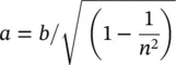
(1.2) 
An integrated elliptical lens antenna is obtained by cutting off the part of the dielectric below the bottom focal point and placing the feeding antenna beneath it. As depicted in Figure 1.10, only rays that hit the surface of the elliptical lens above the plane of its maximum diameter, denoted herein as its waist, are collimated. The portion of the radiated fields intersecting the lens below its waist is not collimated, but rather propagates along undesired directions or excites surface wave modes, thus giving rise to side lobes or other perturbations in the lens’ radiation pattern [20]. One solution to solve this problem is to control the beamwidth of the feed in order that the majority of its radiated energy falls within the angular range above the waist of the lens.
Читать дальшеИнтервал:
Закладка:
Похожие книги на «Advanced Antenna Array Engineering for 6G and Beyond Wireless Communications»
Представляем Вашему вниманию похожие книги на «Advanced Antenna Array Engineering for 6G and Beyond Wireless Communications» списком для выбора. Мы отобрали схожую по названию и смыслу литературу в надежде предоставить читателям больше вариантов отыскать новые, интересные, ещё непрочитанные произведения.


Обсуждение, отзывы о книге «Advanced Antenna Array Engineering for 6G and Beyond Wireless Communications» и просто собственные мнения читателей. Оставьте ваши комментарии, напишите, что Вы думаете о произведении, его смысле или главных героях. Укажите что конкретно понравилось, а что нет, и почему Вы так считаете.