Richard W. Ziolkowski - Advanced Antenna Array Engineering for 6G and Beyond Wireless Communications
Здесь есть возможность читать онлайн «Richard W. Ziolkowski - Advanced Antenna Array Engineering for 6G and Beyond Wireless Communications» — ознакомительный отрывок электронной книги совершенно бесплатно, а после прочтения отрывка купить полную версию. В некоторых случаях можно слушать аудио, скачать через торрент в формате fb2 и присутствует краткое содержание. Жанр: unrecognised, на английском языке. Описание произведения, (предисловие) а так же отзывы посетителей доступны на портале библиотеки ЛибКат.
- Название:Advanced Antenna Array Engineering for 6G and Beyond Wireless Communications
- Автор:
- Жанр:
- Год:неизвестен
- ISBN:нет данных
- Рейтинг книги:3 / 5. Голосов: 1
-
Избранное:Добавить в избранное
- Отзывы:
-
Ваша оценка:
Advanced Antenna Array Engineering for 6G and Beyond Wireless Communications: краткое содержание, описание и аннотация
Предлагаем к чтению аннотацию, описание, краткое содержание или предисловие (зависит от того, что написал сам автор книги «Advanced Antenna Array Engineering for 6G and Beyond Wireless Communications»). Если вы не нашли необходимую информацию о книге — напишите в комментариях, мы постараемся отыскать её.
Reviews advances in the design and deployment of antenna arrays for future generations of wireless communication systems, offering new solutions for the telecommunications industry Advanced Antenna Array Engineering for 6G and Beyond Wireless Communications
Advanced Antenna Array Engineering for 6G and Beyond Wireless Communications
Advanced Antenna Array Engineering for 6G and Beyond Wireless Communications — читать онлайн ознакомительный отрывок
Ниже представлен текст книги, разбитый по страницам. Система сохранения места последней прочитанной страницы, позволяет с удобством читать онлайн бесплатно книгу «Advanced Antenna Array Engineering for 6G and Beyond Wireless Communications», без необходимости каждый раз заново искать на чём Вы остановились. Поставьте закладку, и сможете в любой момент перейти на страницу, на которой закончили чтение.
Интервал:
Закладка:
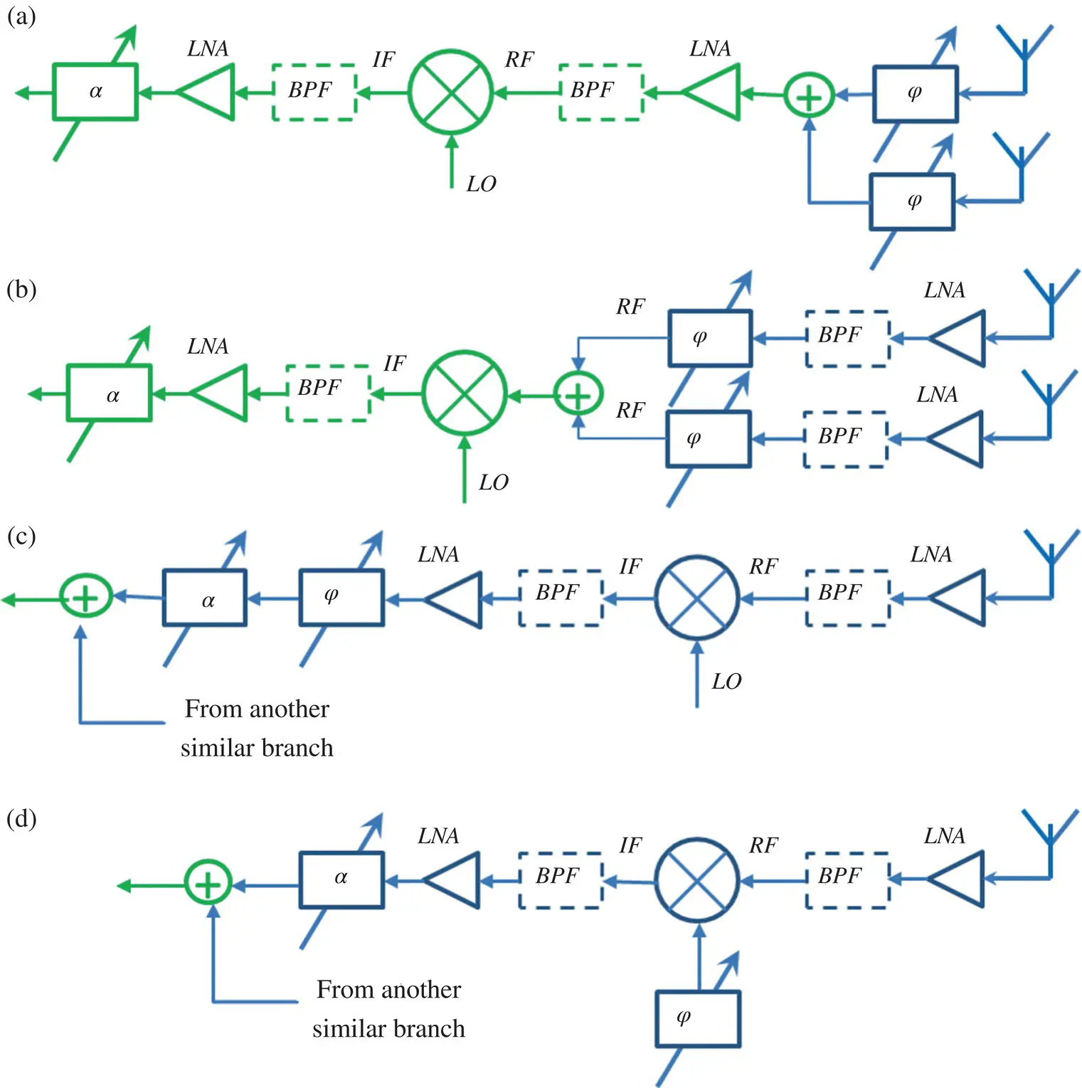
Figure 1.6 Options for implementing analog subarrays. The blocks φ and α denote a variable phase shifter and magnitude attenuator, respectively. Blocks in green represent those able to be shared by the antenna elements in a subarray. The circle with a cross in it denotes where signals from individual antenna elements are combined to be delivered to the shared components. The subfigures show the four main options. (a) Phase shifter at the RF element before an LNA. (b) Phase shifter at the RF element after an LNA. (c) Phase shifter at the IF unit. (d) Phase shifter at the LO unit.
It must be noted that commercial 6‐bit digital phase shifter mm‐wave integrated circuits (MMICs) are available for a range of LO and IF frequencies suitable for mm‐wave arrays. These devices provide 360° of phase change with a least significant bit (LSB) of 5.625°. This resolution allows analog beamforming with a scan angle accuracy to a fraction of a degree. The system configuration in Figure 1.5d is particularly attractive since the devices in the LO path are typically operated in saturation. Consequently, variable losses that usually change with any phase shift are avoided in this scheme.
It is should be pointed out that a more elegant and highly desirable solution to forming multiple beams in a hybrid fashion is to employ analog multi‐beam antennas rather than using subarrays of antenna elements. In principle, the entire antenna aperture can be shared by all the users. However, the generation of multiple individually steerable analog beams is in itself a huge challenge. Unfortunately, there exist only a very limited number of solutions that can be incorporated into the hybrid beamforming configurations discussed above. A number of the remaining chapters in this book will explore various ideas to fill such current technology gaps.
Notice that it is expected that both fully digital beamformers and hybrid beamformers will be employed for 5G deployments. Some of the anticipated use cases envisaged by industry are listed in Table 1.1[4].
Table 1.1 Use cases for digital and hybrid beamforming.
Source : From [4] / with permission of 5G Americas.
| Beamforming type | Use cases |
|---|---|
| Digital beamforming | Sub‐6 GHz massive MIMO: MU‐MIMOSub‐6 GHz macro cell2D beamformingFixed wireless access |
| Hybrid beamforming | mm‐wave based systemsSub‐6 GHz small cells/hot spot coverageFixed wireless accessMassive MIMO macro cells |
1.4 Analog Multiple Beamforming
There are a number of ways to create steerable antenna beams in an analog manner. These include the use of circuit-type beamformers, reflectors, lenses, and phased arrays. These and other more advanced methods will be presented in later chapters. We review some of the basic concepts here.
The most common analog beamforming antennas are phased arrays. The original technology dates back to the mid‐twentieth century. It remained primarily as a military technology until the 5G era. In a phased array, the same signal is fed to each antenna element. The amplitudes of the elements are weighted according to the desired shape of the beam, i.e., the shape of the radiated pattern, and then phase‐shifters are used to steer the beam emitted by the array into the desired direction. In order to save cost, the current commercial 5G mm‐wave systems employ phased arrays to conduct analog beamforming. Both the base station and the user equipment (UE) use a number of fixed weight settings, or sets of phase‐shifting values, to produce different beams pointed in specific directions. There are only two beams pointed in the same direction at any given point of time, each for the horizontal and vertical polarizations, respectively. Consequently, current base stations steer their beams sequentially in different directions to provide the desired coverage. The system capacity could be significantly improved by introducing multiple beams. However, it remains a major technological challenge to provide sufficient flexibility to achieve multiple beam directions with an analog beamforming system.
Phased arrays are inherently suited for producing single beams. Because one signal is fed to all of its elements, a phased array constitutes only one antenna port per beam. The beam is steered to follow the intended user by controlling the values of its phase shifters. Some sacrifices have to be made to produce individually steerable multiple beams with a phased array. They include partitioning the array aperture for different beams; and, hence, this limits the overall performance of each generated beam. In the following subsections, we present two multiple analog beamforming techniques that are currently popular for cellular systems: Butler matrices, and Luneburg lenses.
1.4.1 Butler Matrix
One traditional method of producing multiple beams is to utilize Butler matrices [14]. These multiple beams can be steered together in principle, but not independently. Therefore, Butler matrices are almost exclusively used for fixed beams. A Butler matrix is an RF circuit consisting of couplers, delay lines, crossovers, and transition parts. An n ‐way Butler matrix has n inputs and n outputs. A signal applied to a given input will lead to outputs of equal amplitude but with a uniform phase gradient, thus leading to a single steered beam. The phase increment between adjacent outputs is a multiple of  depending on which input is fed. The phase increment across the outputs, that occurs if input i is fed, is
  , where i can take on integer values from 0 to n − 1. If the n outputs of the Butler matrix are connected to a linear array of n equally spaced radiating elements, a set of n beams equally spaced in angle will be generated if all of the inputs are fed. Figure 1.7shows the configuration of a 4 × 4 Butler matrix and the 4 beams it produces with 4 radiating elements.
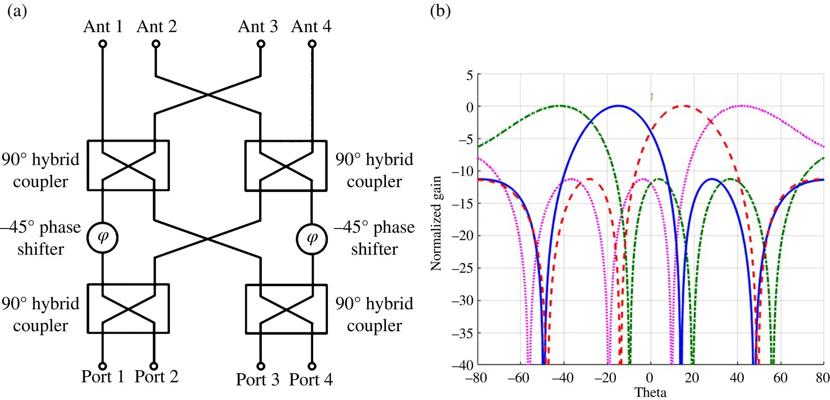
Figure 1.7 Typical implementation of a 4 × 4 Butler matrix (BM) connected to 4 radiating elements and the 4 beams it produces.
Unfortunately, multiple beamforming employing a Butler matrix has a number of disadvantages. First, the beams are fixed. Consequently, it is only a switched beam solution for tracking mobile users. Second, owing to the losses in the Butler matrix’s circuits, a major challenge for large antenna arrays is keeping the overall losses small, especially at millimeter‐wave frequencies. Third, a 2D Butler matrix would be required for two‐dimensional (2D) beamforming. However, the conventional structure is generally too bulky and too lossy owing to the complicated requisite crossovers. Fourth, a complete system engineering approach is required to achieve wideband operation with a Bulter matrix. These issues are only some of the challenges facing the antenna research community. They and some recently developed solutions will be addressed in several later chapters.
1.4.2 Luneburg Lenses
A simple, yet powerful, analog method to create steerable and multiple beams is to employ a spherical Luneburg lens. A Luneburg lens in its simplest form consists of a radially inhomogeneous sphere with a well‐defined graded dielectric constant that varies from 2.0 at the center of the sphere to 1.0 at its outer surface. The gradation is given by the equation: 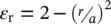 , where ε ris the relative dielectric constant at radius r and a is the outer radius of the sphere. The resulting structure serves to transform rays incident on one side to parallel rays on the opposite side. An antenna feed located on the surface of the lens produces a steered beam if the element moves around the surface as illustrated in Figure 1.8a. The low dielectric constant near the lens surface ensures that no energy is reflected back to the feed. In order to accommodate feeds whose phase centers cannot be placed at the surface of the Luneburg lens, such as a horn antenna, one can modify the distribution of the dielectric constant within the lens [15]. Figure 1.8b shows the corresponding cylindrical version, which is known as a cylindrical Luneburg lens .
Интервал:
Закладка:
Похожие книги на «Advanced Antenna Array Engineering for 6G and Beyond Wireless Communications»
Представляем Вашему вниманию похожие книги на «Advanced Antenna Array Engineering for 6G and Beyond Wireless Communications» списком для выбора. Мы отобрали схожую по названию и смыслу литературу в надежде предоставить читателям больше вариантов отыскать новые, интересные, ещё непрочитанные произведения.


Обсуждение, отзывы о книге «Advanced Antenna Array Engineering for 6G and Beyond Wireless Communications» и просто собственные мнения читателей. Оставьте ваши комментарии, напишите, что Вы думаете о произведении, его смысле или главных героях. Укажите что конкретно понравилось, а что нет, и почему Вы так считаете.