Richard W. Ziolkowski - Advanced Antenna Array Engineering for 6G and Beyond Wireless Communications
Здесь есть возможность читать онлайн «Richard W. Ziolkowski - Advanced Antenna Array Engineering for 6G and Beyond Wireless Communications» — ознакомительный отрывок электронной книги совершенно бесплатно, а после прочтения отрывка купить полную версию. В некоторых случаях можно слушать аудио, скачать через торрент в формате fb2 и присутствует краткое содержание. Жанр: unrecognised, на английском языке. Описание произведения, (предисловие) а так же отзывы посетителей доступны на портале библиотеки ЛибКат.

- Название:Advanced Antenna Array Engineering for 6G and Beyond Wireless Communications
- Автор:
- Жанр:
- Год:неизвестен
- ISBN:нет данных
- Рейтинг книги:3 / 5. Голосов: 1
-
Избранное:Добавить в избранное
- Отзывы:
-
Ваша оценка:
Advanced Antenna Array Engineering for 6G and Beyond Wireless Communications: краткое содержание, описание и аннотация
Предлагаем к чтению аннотацию, описание, краткое содержание или предисловие (зависит от того, что написал сам автор книги «Advanced Antenna Array Engineering for 6G and Beyond Wireless Communications»). Если вы не нашли необходимую информацию о книге — напишите в комментариях, мы постараемся отыскать её.
Reviews advances in the design and deployment of antenna arrays for future generations of wireless communication systems, offering new solutions for the telecommunications industry Advanced Antenna Array Engineering for 6G and Beyond Wireless Communications
Advanced Antenna Array Engineering for 6G and Beyond Wireless Communications
Advanced Antenna Array Engineering for 6G and Beyond Wireless Communications — читать онлайн ознакомительный отрывок
Ниже представлен текст книги, разбитый по страницам. Система сохранения места последней прочитанной страницы, позволяет с удобством читать онлайн бесплатно книгу «Advanced Antenna Array Engineering for 6G and Beyond Wireless Communications», без необходимости каждый раз заново искать на чём Вы остановились. Поставьте закладку, и сможете в любой момент перейти на страницу, на которой закончили чтение.
Интервал:
Закладка:

Figure 1.10 Illustration of (a) an integrated elliptical lens antenna and (b) an extended hemispherical lens antenna.
Another issue arising from the internal reflections at the surface of an elliptical lens is the matching of the feed. One inherent characteristic of elliptical lenses is that all of the reflected rays that pass through the second focal point are reflected back to the first focal point. This reflected power causes a substantial mismatch to the feed impedance. A classical method to address this issue is to enclose the elliptical length with a matching shell that is a quarter‐wave thick. The shell dimensions are specified according to the following equations:
(1.3) 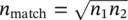
(1.4) 
where n 1, n 2, and n matchrepresent the refraction indexes of the lens, the air, and the matching shell. The main drawback of this approach is that the improved matching performance can only be maintained within a relatively narrow bandwidth. To improve the bandwidth, one can incorporate multiple consecutive matching layers to perform a gradual transition between the two dielectric constants across each interface.
Since the collimation from an elliptical lens only occurs for the portion of the wave front that impinges on its front surface, the part below its waist can be replaced with a cylinder. Furthermore, the top elliptical part, the hemi‐ellipse, can be approximated by a hemisphere. This modification significantly reduces the fabrication complexity. The difference in the height of the hemi‐ellipse and the hemisphere can be compensated by the height of the cylindrical extension. This new lens is known as an extended hemispherical lens. It turns out to be a rather good approximation to a true elliptical lens, although it tends to present a slightly lower directivity compared to one having the same diameter. The relationship between the radius of the hemisphere, R ; the height of the cylinder under it, L ; and the refraction index of the lens material, n , is given by
(1.5) 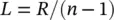
A lens similar to the extended hemispherical lens is known as a hyper hemispherical lens. In contrast to Eq. (1.5), the cylindrical extension length is now given by [23]:
(1.6) 
The rays at the output of the hyper hemispherical lens are not collimated. Therefore, the beam that it generates is much broader than that of the extended hemispherical lens. Nevertheless, it does sharpen the beam radiated by the feed antenna and increases its gain by a factor of n 2. However, unlike the collimating lenses, the directivity of this lens does not increase with the lens size, i.e., its aperture size. The hyper hemispherical length satisfies the Abbe sine condition so the lens itself is free from coma aberration when the feed is transversely displaced from the lens axis [25]. Therefore, it is well suited for beam steering.
It must be noted that Eqs. (1.5)and (1.6)are based simply on geometrical optics and point source assumptions. For actual antenna designs at mm‐wave and THz frequencies, optimization of the cylindrical extension would be required to achieve the optimal radiation performance [26, 27].
Another type of lenses for mm‐wave and THz operations is the Fresnel lens [28]. A Fresnel lens consists of a number of alternately transparent and opaque half‐wave zones. The source of the antenna is placed at its focal point. The opaque zones are attained by covering the corresponding portions of the lens with conducting or absorbing materials. Figure 1.11a shows a circular Fresnel lens. It consists of a series of zonal openings in a finite conducting sheet. To increase the antenna efficiency and reduce the sidelobe level, one can introduce phase correcting elements into the zones as depicted in Figure 1.11b [29]. The resulting radiator is effectively a transmit array.
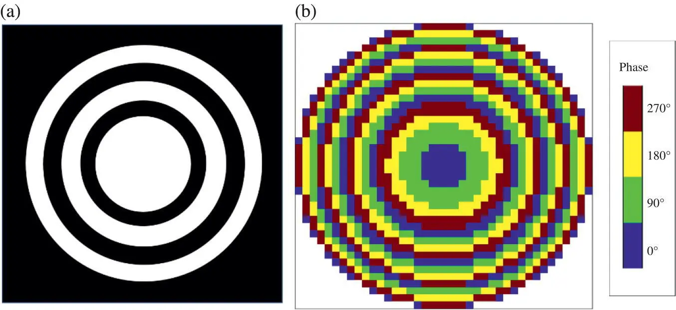
Figure 1.11 Illustration of Fresnel lenses. (a) Original Fresnel lens. (b) Circular phase correcting version [29].
Source : Modified from [25] / IEEE.
One salient advantage of the Fresnel lens is its low profile. On the other hand, its main disadvantage is its relatively narrow bandwidth. Nevertheless, substantial progress has been made to increase the bandwidth of transmit arrays in recent years [30]. It should be pointed out that although a Fresnel lens can be made flat, it still needs a feed typically placed many wavelengths away from the lens. If the required beamwidth is not too narrow, one can achieve a completely flat version, i.e., a metasurface‐based antenna that is created by placing a metasurface above an antenna backed by a ground plane [31].
1.8 SIMO and MIMO Multi‐Beam Antennas
Before we end this chapter, we would like to clarify the concept of multi‐beam antennas. A conventional antenna has only one input port for one single beam with a specified polarization. We call such an antenna a single input and single output (SISO) antenna. There are two options to create multiple beams. The first option is that a single signal is fed into one port and then is split or distributed to sets of radiating elements and, hence, into a number of beams. We call this type of antenna a single input and multiple output (SIMO) multi‐beam antenna; it is illustrated in Figure 1.12a. The second option is that multiple signals are fed into multiple ports, separately, and then each input signal is delivered to a specific set of radiating elements to produce one dedicated beam. We call this type of antenna a multiple input and multiple output (MIMO) multi‐beam antenna; it is illustrated in Figure 1.12b. SIMO multi‐beam antennas are useful for data distribution and targeted broadcasting services. On the other hand, MIMO multi‐beam antennas are useful for multiuser communications in which each user is at a different location and communicates different information. The multiple beams created by SIMO and MIMO antennas can be fixed or steerable. The latter is much harder to achieve and would serve as a major research direction for the future. This topic is addressed further in Chapters 5and 6.
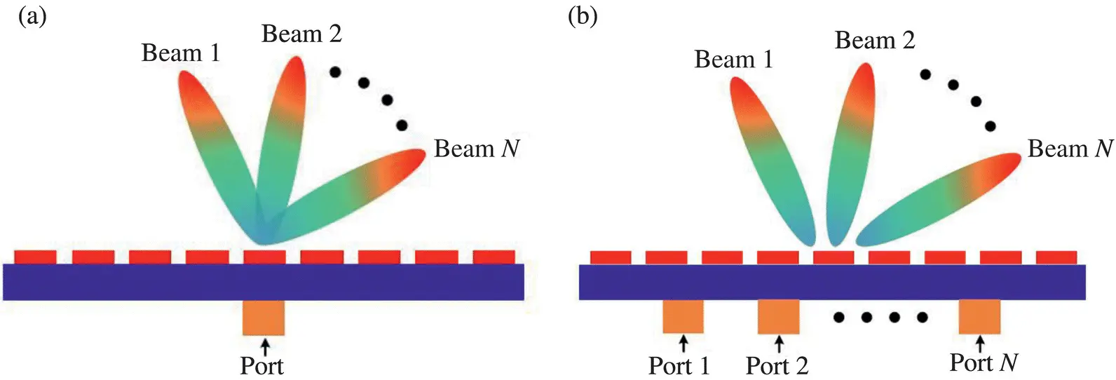
Figure 1.12 Illustration of (a) SIMO and (b) MIMO multi‐beam antennas.
Notice that the SIMO and MIMO multi‐beam antenna concepts presented above are substantially different from the concepts of SIMO and MIMO in wireless communication systems. All of the inputs and outputs in the former reside in one transmitter or receiver system, typically in the base stations. The multi‐beams produced by the antennas are distinct beam patterns. In contrast, all of the inputs and outputs of the latter reside separately in the transmitter, typically at the base station, and the receivers, typically in the user terminals. The transmitted RF signal may not have distinct conventional beam patterns; certain types of multiuser detection or spatial–temporal decoding algorithms are employed at the receivers with no regard to specific beam patterns.
Читать дальшеИнтервал:
Закладка:
Похожие книги на «Advanced Antenna Array Engineering for 6G and Beyond Wireless Communications»
Представляем Вашему вниманию похожие книги на «Advanced Antenna Array Engineering for 6G and Beyond Wireless Communications» списком для выбора. Мы отобрали схожую по названию и смыслу литературу в надежде предоставить читателям больше вариантов отыскать новые, интересные, ещё непрочитанные произведения.


Обсуждение, отзывы о книге «Advanced Antenna Array Engineering for 6G and Beyond Wireless Communications» и просто собственные мнения читателей. Оставьте ваши комментарии, напишите, что Вы думаете о произведении, его смысле или главных героях. Укажите что конкретно понравилось, а что нет, и почему Вы так считаете.