Richard W. Ziolkowski - Advanced Antenna Array Engineering for 6G and Beyond Wireless Communications
Здесь есть возможность читать онлайн «Richard W. Ziolkowski - Advanced Antenna Array Engineering for 6G and Beyond Wireless Communications» — ознакомительный отрывок электронной книги совершенно бесплатно, а после прочтения отрывка купить полную версию. В некоторых случаях можно слушать аудио, скачать через торрент в формате fb2 и присутствует краткое содержание. Жанр: unrecognised, на английском языке. Описание произведения, (предисловие) а так же отзывы посетителей доступны на портале библиотеки ЛибКат.
- Название:Advanced Antenna Array Engineering for 6G and Beyond Wireless Communications
- Автор:
- Жанр:
- Год:неизвестен
- ISBN:нет данных
- Рейтинг книги:3 / 5. Голосов: 1
-
Избранное:Добавить в избранное
- Отзывы:
-
Ваша оценка:
Advanced Antenna Array Engineering for 6G and Beyond Wireless Communications: краткое содержание, описание и аннотация
Предлагаем к чтению аннотацию, описание, краткое содержание или предисловие (зависит от того, что написал сам автор книги «Advanced Antenna Array Engineering for 6G and Beyond Wireless Communications»). Если вы не нашли необходимую информацию о книге — напишите в комментариях, мы постараемся отыскать её.
Reviews advances in the design and deployment of antenna arrays for future generations of wireless communication systems, offering new solutions for the telecommunications industry Advanced Antenna Array Engineering for 6G and Beyond Wireless Communications
Advanced Antenna Array Engineering for 6G and Beyond Wireless Communications
Advanced Antenna Array Engineering for 6G and Beyond Wireless Communications — читать онлайн ознакомительный отрывок
Ниже представлен текст книги, разбитый по страницам. Система сохранения места последней прочитанной страницы, позволяет с удобством читать онлайн бесплатно книгу «Advanced Antenna Array Engineering for 6G and Beyond Wireless Communications», без необходимости каждый раз заново искать на чём Вы остановились. Поставьте закладку, и сможете в любой момент перейти на страницу, на которой закончили чтение.
Интервал:
Закладка:
The simplest spatial multiplexing scheme is to employ sectorized antennas, a conventional technique for frequency reuse. More advanced spatial multiplexing schemes employ spatial–temporal (or frequency) coding by virtue of multiple input and multiple output (MIMO) antennas. A MIMO system requires the use of multiple antennas at least at the base stations. MIMO is implemented with two basic schemes as described below.
The first spatial multiplexing scheme is known as single user MIMO (SU‐MIMO). By virtue of multiple antennas at both the base station and the user terminals, SU‐MIMO first splits the data stream transmitted toward a specific user into multiple data streams. It then recombines them together at the user terminal to improve the information throughput and system capacity. One major challenge to SU‐MIMO is the need for the tightly packed multiple antennas in the terminals to be decoupled.
The second spatial multiplexing scheme is known as multiuser MIMO (MU‐MIMO). MU‐MIMO aims to maximize the overall data throughput between all of the users and their associated base station. While it employs an antenna array at the base station, only one or a few antenna elements are present at each user terminal. Since user terminals are typically well dispersed within a radio cell and their individual channels are likely to be uncorrelated, the benefits of MU‐MIMO are easier to achieve.
Both SU‐MIMO and MU‐MIMO protocols are intended for implementation in most 5G systems.
c) Beamforming
Spatial filtering can be regarded as a simple version of MU‐MIMO. Beamforming achieves this spatial filtering by coherently combining the fields radiated by the array elements to direct their radiated energy into particular directions. These multiple beams are created at the base station to communicate with different users simultaneously.
Beamforming offers two benefits to a communication system. The first is capacity. If there is no overlap of the beams, simultaneous communications can take place in the same frequency band and at the same time without causing much interference. The second is the gain of the antenna array. Higher gain translates into information exchange over greater distances or higher data rates due to increased SINR values. Unlike 3G and 4G antenna arrays that provide coverage with fixed beam patterns and directivity, 5G arrays must support on‐demand beam coverage according to real‐time application scenarios and user distributions. Moreover, they must be able to support beam management in order to deliver precise coverage in target areas while significantly suppressing interference in other areas.
For beamforming to be effective, large antenna arrays are necessary to generate narrow beams and produce scattering from mobile users with small angular spreads. The latter is to ensure that the majority of the signals transmitted and received from a mobile platform is covered by a narrow base station antenna beam. These requirements, in conjunction with wide bandwidths, support the use of millimeter wave (mm‐wave) communications for 5G. In particular, mm‐waves propagate in a pseudo‐light fashion so the scattering of the signals to and from a mobile platform is highly localized. Furthermore, since their wavelengths are small, an electrically large mm‐wave array can be fit easily into a physically small space.
1.1.2 Frequency Bands
Another major challenge associated with 5G antenna arrays is the simultaneous support of all allotted frequency bands [6]. As the number of bands being considered to meet current and future 5G needs increases, significant antenna array innovations are required to support all of them. Moreover, existing 4G bands must be supported as well [7].
Owing to the stringent requirements placed on the radiation patterns produced by cellular systems and on the levels of their impedance matching to sources to maximize their realized gains, the mobile communication industry has so far adopted an approach of using different antennas to support different frequency bands. However, because of the limited space at base station antenna sites and in mobile platforms, the coexistence of these different antennas has posed serious challenges already. It is extremely difficult to maintain low coupling levels between antennas operating over the same band and even harder to suppress the scattering interactions between antennas that operate over different bands. The latter can cause significant distortions to the radiation patterns. It is with this background that the decoupling and de‐scattering issues will be addressed in Chapters 2and 3, respectively.
1.1.3 Component Integration and Antennas‐in‐Package (AiP)
Clearly, the number of antenna ports and radios for 5G systems will grow dramatically with the increasing numbers of massive antenna arrays and operating bands. This growth implies that the number of cables that connect the radios to the antennas would increase accordingly. This increase necessarily leads to increased fabrication complexities, losses in the cables and connectors, and difficulties in the control of passive intermodulation (PIM) and testing. To mitigate these problems, one needs to change antenna system design methodologies to introduce much higher levels of integration. To this end, there has been a high expectation that 5G antennas, the mm‐wave band antennas in particular, will become highly integrated systems.
Integrated antenna and radio systems eliminate the need for multiple cables between the radios and antennas, thus increasing their reliability by reducing part counts and handling, and simplifying their testing and installation. As a result, there has been an increasing need for effective antenna‐in‐package (AiP) solutions. In addition to managing the radiation performance of the antenna elements and arrays, one must consider several issues for AiP designs. These include, for instance, the materials; process selection and control; power and heat management; and new testing techniques. As an example, Figure 1.1shows a 64‐element AiP system at 28 GHz. It has four flip‐chip‐mounted transceiver ICs that support its dual‐polarized operation [8]. For clarity, the heat sink below the ball‐grid‐array (BGA) interface is not shown.
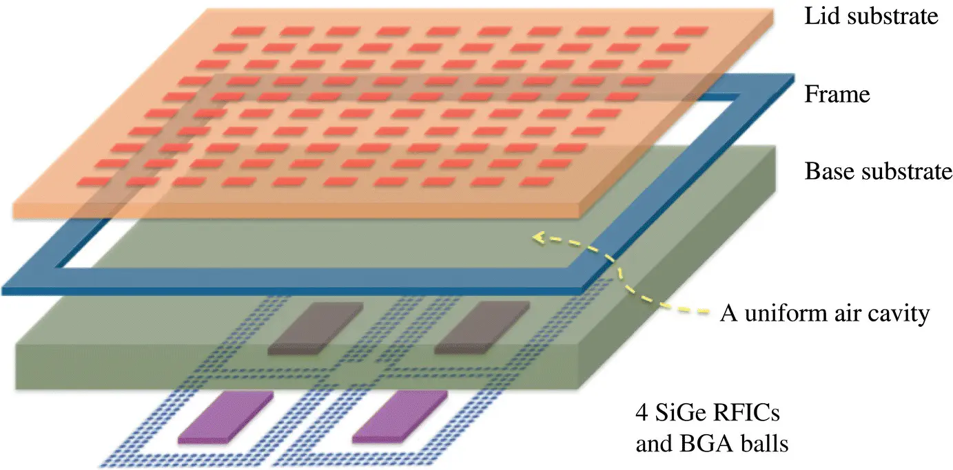
Figure 1.1 An illustration of a 64‐element antenna‐in‐package (AiP) assembly breakout.
Source : From [8] / with permission of IEEE.
One particular new challenge associated with highly integrated 5G antenna arrays is obtaining accurate antenna beam patterns. Depending on their actual implementation, methods for testing active antennas vary. Current examples include the following [4]:
a) Sample Testing
This approach involves the fabrication of a number of fixed analog beamforming circuits that provide the requisite amplitude and phase excitations to the antenna array to produce the desired beams including narrow beams for user traffic and broad beams for user management. Each circuit produces one specific beam. This allows one to sample each of the desired beam types and steering directions. For practical reasons, it is difficult to perform a comprehensive test of all of the possible beams generated by a large array. Therefore, only those beams of greatest interest are likely to be tested.
b) Element‐by‐Element Testing
The far‐field vectorial pattern of each element, i.e., the amplitude and phase distribution in the far‐field of the array, can be measured with respect to a common reference. Any beamforming pattern can then be synthesized numerically by adding all the element patterns with the corresponding appropriate complex weights. This approach is the most flexible method since all possible patterns can be tested. Nevertheless, one can argue realistically that the synthesized beam patterns may differ from the real ones to a certain extent because all of the actual interactions are not explicitly included.
Читать дальшеИнтервал:
Закладка:
Похожие книги на «Advanced Antenna Array Engineering for 6G and Beyond Wireless Communications»
Представляем Вашему вниманию похожие книги на «Advanced Antenna Array Engineering for 6G and Beyond Wireless Communications» списком для выбора. Мы отобрали схожую по названию и смыслу литературу в надежде предоставить читателям больше вариантов отыскать новые, интересные, ещё непрочитанные произведения.


Обсуждение, отзывы о книге «Advanced Antenna Array Engineering for 6G and Beyond Wireless Communications» и просто собственные мнения читателей. Оставьте ваши комментарии, напишите, что Вы думаете о произведении, его смысле или главных героях. Укажите что конкретно понравилось, а что нет, и почему Вы так считаете.