Mohamed N. Rahaman - Materials for Biomedical Engineering
Здесь есть возможность читать онлайн «Mohamed N. Rahaman - Materials for Biomedical Engineering» — ознакомительный отрывок электронной книги совершенно бесплатно, а после прочтения отрывка купить полную версию. В некоторых случаях можно слушать аудио, скачать через торрент в формате fb2 и присутствует краткое содержание. Жанр: unrecognised, на английском языке. Описание произведения, (предисловие) а так же отзывы посетителей доступны на портале библиотеки ЛибКат.
- Название:Materials for Biomedical Engineering
- Автор:
- Жанр:
- Год:неизвестен
- ISBN:нет данных
- Рейтинг книги:4 / 5. Голосов: 1
-
Избранное:Добавить в избранное
- Отзывы:
-
Ваша оценка:
Materials for Biomedical Engineering: краткое содержание, описание и аннотация
Предлагаем к чтению аннотацию, описание, краткое содержание или предисловие (зависит от того, что написал сам автор книги «Materials for Biomedical Engineering»). Если вы не нашли необходимую информацию о книге — напишите в комментариях, мы постараемся отыскать её.
A comprehensive yet accessible introductory textbook designed for one-semester courses in biomaterials Materials for Biomedical Engineering: Fundamentals and Applications
Materials for Biomedical Engineering: Fundamentals and Applications
Materials for Biomedical Engineering — читать онлайн ознакомительный отрывок
Ниже представлен текст книги, разбитый по страницам. Система сохранения места последней прочитанной страницы, позволяет с удобством читать онлайн бесплатно книгу «Materials for Biomedical Engineering», без необходимости каждый раз заново искать на чём Вы остановились. Поставьте закладку, и сможете в любой момент перейти на страницу, на которой закончили чтение.
Интервал:
Закладка:
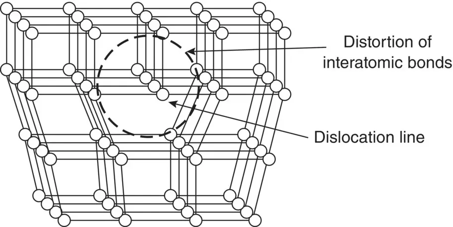
Figure 3.18 Schematic representation of a dislocation in a crystal and the distortion of the interatomic bonds in its immediate vicinity.
Dislocations can become more numerous when a metal is deformed under appropriate mechanical stresses such as those during rolling or extrusion, thereby enhancing the strain energy of the crystals. Practically, deformation of a metal to increase its strain energy followed by thermal treatment of the highly strained material is one of the common methods used to control the microstructure of a metal and, thus, its mechanical properties ( Chapter 6).
In comparison, dislocations are unimportant in the majority of ceramics at ordinary temperatures. A considerably higher amount of energy is required for the creation and migration of dislocations in ceramics due to their strong ionic or covalent bonding, and their composition composed of two or more dissimilar atoms. Consequently, the dislocation density (number of dislocations per unit volume) is low or negligible, and the role of dislocations can be neglected in the majority of ceramics, including those used as biomaterials such as aluminum oxide, hydroxyapatite, and β‐tricalcium phosphate.
Types of Dislocations
Dislocations are divided into two basic types, called edge dislocations and screw dislocations ( Figure 3.19) but they are often more complex in real crystals, composed of some mixture of these two basic types. In a simple sense, an edge dislocation can be visualized as making a cut in a perfect crystal and inserting an additional half‐plane of atoms. The edge of the half‐plane of atoms within the crystal is the dislocation line, that is, defects along a line of atomic sites. Instead of inserting an extra half‐plane of atoms after making a cut in the crystal, we can displace one part of the crystal relative to the other part in a direction parallel to the bottom of the cut. This gives the other basic type of dislocation, called a screw dislocation because, if traced in the direction of the dislocation line, the planes of atoms form a helical surface or a screw.
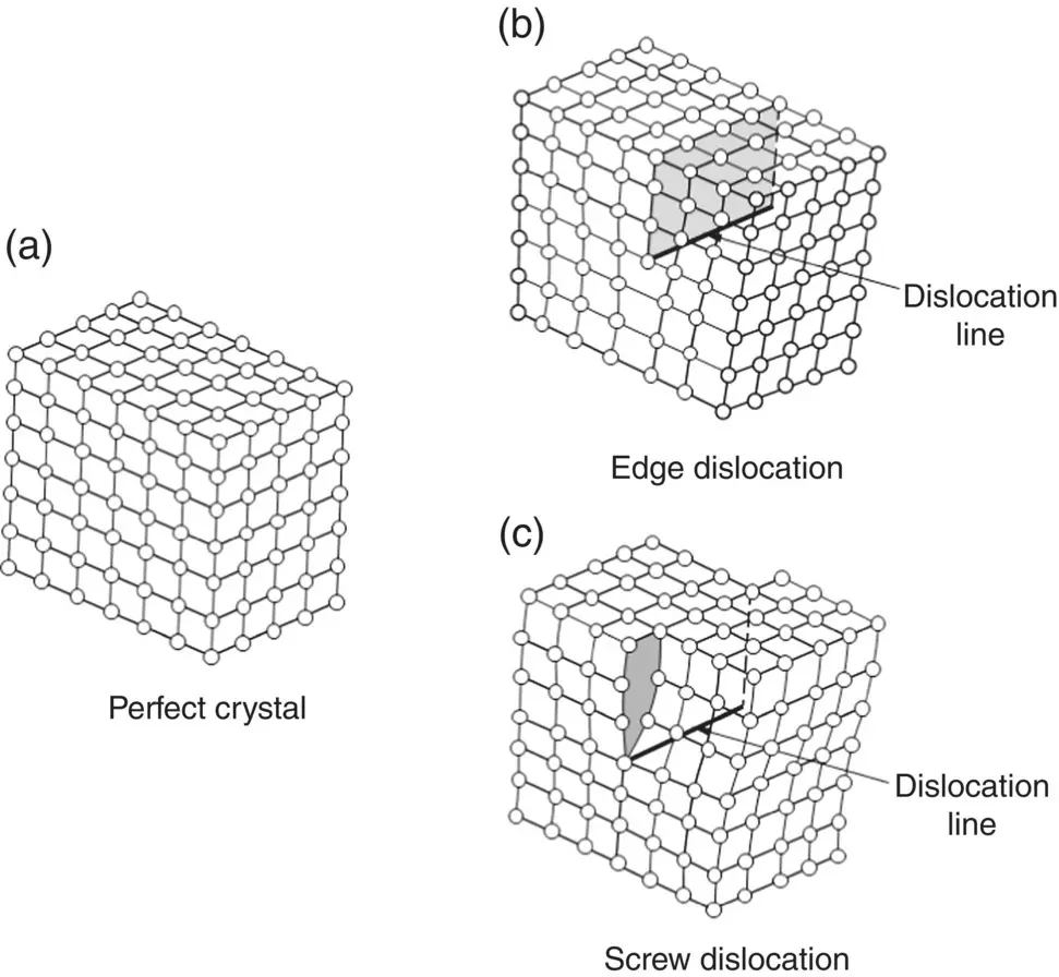
Figure 3.19 Schematic representation of part of a perfect crystal (a) and the arrangement of atoms near the two basic types of dislocations, edge dislocation (b) and screw dislocation (c).
Slip or Plastic Deformation Resulting from Dislocation Motion
When a crystal containing edge dislocations is subjected to a sufficiently high mechanical stress, one plane of atoms slides or is successively displaced over atoms in the adjacent plane in a direction perpendicular to the dislocation line. However, all the atoms in one plane do not slide simultaneously over those in the adjacent plane. Instead, the atomic bonds across the plane of displacement break and reform one at a time ( Figure 3.20). Complete movement of the dislocation through the crystal results in permanent displacement of one plane of atoms over the other plane. This type of deformation is called plastic deformation or slip, because, unlike elastic deformation, the atoms do not return to their original positions upon release of the mechanical stress ( Chapter 4). Although the geometry of a screw dislocation is more complicated, its properties are similar to those described for the edge dislocation.
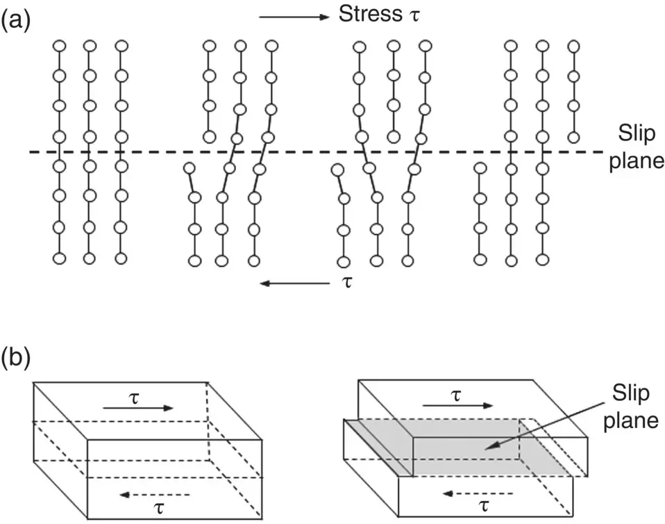
Figure 3.20 Schematic representation of the movement of an edge dislocation through a crystal. The atomic bonds at the center of the dislocation break and reform in a sequential manner, allowing the dislocation to move. Complete movement of the dislocation through the crystal results in slip of one part of the crystal over the other part.
If a perfect crystal is subjected to tensile loading, the stress required to simultaneously rupture all the bonds across a plane and cause fracture is defined as the ideal strength or theoretical strength of the crystal. Theoretical analysis shows that the ideal strength of a crystal is in the range approximately E /3 to E /8, where E is the elastic modulus in tensile loading called the Young’s modulus ( Chapter 4). Measurements show that when a metal is loaded in tension, the stress required to cause plastic deformation, called the yield stress, is considerably lower than the ideal strength, by a factor of approximately 10 2–10 6depending on the purity and composition of the metal. This is because plastic deformation of a crystal by dislocations motion is far easier and requires far less mechanical stress or energy due to the sequential breaking and reforming of the atomic bonds. This ability to deform rather than fracture suddenly in a brittle manner at some higher stress is responsible for the attractive property of ductility shown by metals.
Another property of dislocation motion is that slip occurs along preferred planes and in preferred directions in these planes, and not just in any plane or direction ( Figure 3.21). Of the possible slip planes and directions in a crystal, under a specific set of conditions, slip normally occurs in a plane in which the atoms have the closest packing and in a direction in this close‐packed plane which has the closest spacing (that is, in a close‐packed direction) ( Table 3.3). This is because a lower amount of energy is required for the dislocation to move in a close‐packed direction of a close‐packed plane due to the smaller distance that an atom has to move from one atomic position to a neighboring position.
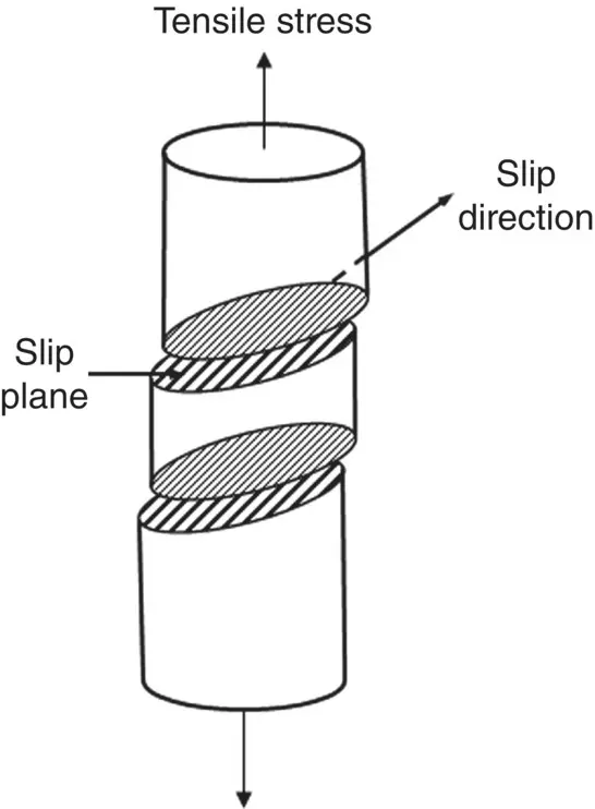
Figure 3.21 Schematic representation of slip in a metal that is subjected to a tensile stress. Slip occurs preferentially along closed‐packed planes and in close‐packed directions in these planes.
Table 3.3 Characteristic properties of the three common metallic structures.
| Structure | N | CN | PD (%) | Slip planes/number | Slip directions/number | Slip system per unit cell |
|---|---|---|---|---|---|---|
| BCC | 2 | 8 | 68 | {110} | 〈111〉 | 6 × 2 = 12 |
| 6 | 2 | |||||
| FCC | 4 | 12 | 74 | {111} | 〈110〉 | 4 × 3 = 12 |
| 4 | 3 | |||||
| CPH | 6 | 12 | 74 | (0001) | 〈11  0〉 0〉 |
1 × 3 = 3 |
| 1 | 3 |
N, number of atoms per unit cell; CN, coordination number (number of atoms surrounding a given atom); PD, packing density.
3.4.3 Planar Defects: Surfaces and Grain Boundaries
Unless formed under highly controlled and, often, expensive conditions, metals and ceramics do not consist of a single crystal. Instead, they are composed of a large number of small crystals, called grains, of size approximately a fraction of a micron to several tens of microns ( Figure 3.22). The material is described as polycrystalline. At the two‐dimensional interface where two grains meet, called the grain boundary, the atoms do not pack in an ordered crystalline arrangement because the atomic planes in adjacent grains have different orientations. Consequently, the grain boundary is generally considered a two‐dimensional or planar defect in crystalline solids. However, it is not an infinitesimally thin plane. Electron microscopy has shown that the grain boundary in pure solids is 0.5–1.0 nm wide and, in this region, the atoms are more loosely packed when compared to the atoms within the crystal itself. The presence of grain boundaries have a strong influence on several properties of polycrystalline materials. As the atoms are more loosely packed, grain boundaries provide an easier path for atoms to migrate through the material. Grain boundaries also obstruct the motion of dislocations due to the looser atomic packing and the change in lattice orientation, a property that is used in controlling the strength and ductility of metals ( Chapter 6).
Читать дальшеИнтервал:
Закладка:
Похожие книги на «Materials for Biomedical Engineering»
Представляем Вашему вниманию похожие книги на «Materials for Biomedical Engineering» списком для выбора. Мы отобрали схожую по названию и смыслу литературу в надежде предоставить читателям больше вариантов отыскать новые, интересные, ещё непрочитанные произведения.


Обсуждение, отзывы о книге «Materials for Biomedical Engineering» и просто собственные мнения читателей. Оставьте ваши комментарии, напишите, что Вы думаете о произведении, его смысле или главных героях. Укажите что конкретно понравилось, а что нет, и почему Вы так считаете.