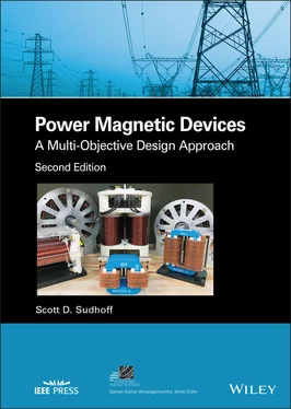
Scott D. Sudhoff - Power Magnetic Devices
Здесь есть возможность читать онлайн «Scott D. Sudhoff - Power Magnetic Devices» — ознакомительный отрывок электронной книги совершенно бесплатно, а после прочтения отрывка купить полную версию. В некоторых случаях можно слушать аудио, скачать через торрент в формате fb2 и присутствует краткое содержание. Жанр: unrecognised, на английском языке. Описание произведения, (предисловие) а так же отзывы посетителей доступны на портале библиотеки ЛибКат.
- Название:Power Magnetic Devices
- Автор:
- Жанр:
- Год:неизвестен
- ISBN:нет данных
- Рейтинг книги:4 / 5. Голосов: 1
-
Избранное:Добавить в избранное
- Отзывы:
-
Ваша оценка:
- 80
- 1
- 2
- 3
- 4
- 5
Power Magnetic Devices: краткое содержание, описание и аннотация
Предлагаем к чтению аннотацию, описание, краткое содержание или предисловие (зависит от того, что написал сам автор книги «Power Magnetic Devices»). Если вы не нашли необходимую информацию о книге — напишите в комментариях, мы постараемся отыскать её.
Discover a cutting-edge discussion of the design process for power magnetic devices Power Magnetic Devices: A Multi-Objective Design Approach
Power Magnetic Devices
Power Magnetic Devices — читать онлайн ознакомительный отрывок
Ниже представлен текст книги, разбитый по страницам. Система сохранения места последней прочитанной страницы, позволяет с удобством читать онлайн бесплатно книгу «Power Magnetic Devices», без необходимости каждый раз заново искать на чём Вы остановились. Поставьте закладку, и сможете в любой момент перейти на страницу, на которой закончили чтение.
Интервал:
Закладка:
8 Chapter 8Figure 8.1 Distributed winding stator.Figure 8.2 Definition of position measurements.Figure 8.3 P ‐pole machines.Figure 8.4 Slot structure.Figure 8.5 Developed diagram.Figure 8.6 End conductors.Figure 8.7 Stator winding for a 4‐pole 36‐slot machine.Figure 8.8 Winding arrangements.Figure 8.9 Calculation of the winding function.Figure 8.10 Conductor distribution and winding functions.Figure 8.11 Path of integration.Figure 8.12 Calculation of flux linkage.Figure 8.13 Carter’s coefficient.Figure 8.14 Slot leakage inductance.Figure 8.15 End leakage inductance.Figure 8.16 Slot leakage permeance due to paths 1–4.Figure 8.17 Slot leakage permeance due to paths 5–7.Figure 8.18 End winding permeance—exterior path.Figure 8.19 Geometric interpretation of Park’s transformation.
9 Chapter 9Figure 9.1 Surface‐mounted permanent magnet synchronous machine.Figure 9.2 Two interior magnetic arrangements.Figure 9.3 Wye and delta connections.Figure 9.4 Three‐phase bridge inverter and machine.Figure 9.5 Voltage source fed PMAC machine characteristics.Figure 9.6 Current source fed PMAC machine characteristics.Figure 9.7 Surface‐mounted permanent magnet synchronous machine.Figure 9.8 Slot and tooth dimensions.Figure 9.9 Rectangular slot approximation.Figure 9.10 Thin sector of machine.Figure 9.11 Radial magnetization.Figure 9.12 Backiron flux calculation.Figure 9.13 Backiron flux.Figure 9.14 Flux density in rotor backiron.Figure 9.15 Pareto‐optimal front.Figure 9.16 Parameter distribution.Figure 9.17 Material selection versus electromagnetic mass.Figure 9.18 Power loss components versus electromagnetic mass.Figure 9.19 Component mass versus electromagnetic mass.Figure 9.20 Current‐related parameters versus electromagnetic mass.Figure 9.21 Machine parameters versus electromagnetic mass.Figure 9.22 Design 38 cross section.Figure 9.23 Design 38 flux density versus rotor position.
10 Chapter 10Figure 10.1 An elemental cuboid.Figure 10.2 One‐dimensional heat flow example.Figure 10.3 Thermal equivalent circuit for one‐dimensional heat flow.Figure 10.4 Mean temperature versus time.Figure 10.5 Heat transfer rate versus time.Figure 10.6 Temperature profile versus time.Figure 10.7 Special case for one‐dimensional heat flow.Figure 10.8 Thermal equivalent circuit of a cuboidal region. (Based on [1].)...Figure 10.9 Cylindrical region.Figure 10.10 Thermal equivalent circuit of cylindrical region.Figure 10.11 Representation of homogenized region. (Based on [2].)Figure 10.12 Spatial temperature dependence.Figure 10.13 Standard branch.Figure 10.14 Concise circuit symbols.Figure 10.15 Thermal equivalent circuit elements.Figure 10.16 Cuboids of EI core electromagnet arrangement.Figure 10.17 Corner element.Figure 10.18 Core‐winding interface.Figure 10.19 Electromagnet thermal equivalent circuit.Figure 10.20 Pareto‐optimal fronts.Figure 10.21 Gene distribution.Figure 10.22 Current density versus volume.Figure 10.23 Conductor counts versus volume.Figure 10.24 Widths versus volume.Figure 10.25 Assorted dimensions versus volume.Figure 10.26 Peak winding temperature versus volume.
11 Chapter 11Figure 11.1 Strip conductor.Figure 11.2 Current density distribution in a strip conductor.Figure 11.3 Impedance characteristics of a strip conductor.Figure 11.4 Cylindrical conductor.Figure 11.5 Impedance characteristic of a cylindrical conductor.Figure 11.6 Rectangular conductor exposed to a magnetic field.Figure 11.7 Round conductor exposed to a magnetic field.Figure 11.8 Current density in a symmetric conductor.Figure 11.9 Gapped closed slot conductors.Figure 11.10 Slot geometry.Figure 11.11 Predicted and measured resistance of a coil in an open slot.Figure 11.12 UI‐core inductor.Figure 11.13 Assumed current waveform.Figure 11.14 Buck converter.Figure 11.15 Conductor losses.
12 Chapter 12Figure 12.1 Inductor equivalent circuit.Figure 12.2 Electric field at a conductor’s surface.Figure 12.3 Parallel plate capacitor.Figure 12.4 Cylindrical plate capacitor.Figure 12.5 Conductor and quasi‐conductor.Figure 12.6 Capacitance of conductive cylinders.Figure 12.7 Turn‐to‐turn capacitance of a simple coil.Figure 12.8 Symmetry conditions for capacitance.Figure 12.9 Turn‐to‐turn capacitance in multilayer windings.Figure 12.10 Calculation of layer‐to‐layer capacitance.Figure 12.11 Core‐type transformer.Figure 12.12 Transformer equivalent circuit.Figure 12.13 Photograph of inductors for Examples 12.3A (leftmost), 12.4 A (...Figure 12.14 Full impedance frequency response of a two‐layer inductor.Figure 12.15 Measured and fitted impedance frequency responses.
13 Chapter 13Figure 13.1 Buck converter.Figure 13.2 Buck converter operation.Figure 13.3 Buck converter average‐value model.Figure 13.4 Input filter waveforms.Figure 13.5 Output filter waveforms.Figure 13.6 Semiconductor/heat‐sink thermal‐equivalent circuit.Figure 13.7 Semiconductor loss versus current ripple.Figure 13.8 Required heat‐sink mass versus current ripple.Figure 13.9 Input inductor mass versus inductance.Figure 13.10 Input inductor loss versus inductance.Figure 13.11 UI‐core inductor.Figure 13.12 Cross‐section of the winding bundle.Figure 13.13 Winding bundle thermal‐equivalent circuit.Figure 13.14 Simplified winding bundle thermal‐equivalent circuit.Figure 13.15 Buck converter parameter distribution.Figure 13.16 Buck converter Pareto‐optimal front.Figure 13.17 Efficiency versus specific power density.Figure 13.18 Switching frequency versus mass.Figure 13.19 UI‐core output inductor cross section.
14 Chapter 14Figure 14.1 A dc–ac converter.Figure 14.2 Phase leg of three‐phase bridge converter.Figure 14.3 Sine‐triangle modulation.Figure 14.4 Inductor topology.Figure 14.5 Time‐domain waveforms with L d= L q.Figure 14.6 Time‐domain waveforms with L d≠ L q.Figure 14.7 Elementary three‐phase inductor MEC.Figure 14.8 The three‐phase inductor MEC.Figure 14.9 Interior and exterior fringing and leakage paths.Figure 14.10 Face fringing and leakage permeances.Figure 14.11 Test points.Figure 14.12 Case study assumed current waveforms.Figure 14.13 Three‐Phase I‐Core inductor parameter distribution.Figure 14.14 Three‐Phase I‐Core inductor pareto‐optimal front.Figure 14.15 Design 100. Dimensions in meters.
15 Chapter 15Figure 15.1 Differential‐ and common‐mode currents.Figure 15.2 Dc‐to‐ac converter.Figure 15.3 Power block.Figure 15.4 Common‐mode equivalent circuit.Figure 15.5 Simplified common‐mode equivalent circuits.Figure 15.6 Common‐mode flux‐linkage waveform.Figure 15.7 Peak common‐mode flux linkage versus duty cycle.Figure 15.8 Original and proxy common‐mode flux‐linkage waveforms.Figure 15.9 CMI circuit diagram.Figure 15.10 UR‐core common‐mode inductor.Figure 15.11 Winding cross section.Figure 15.12 UR core magnetic analysis.Figure 15.13 UR‐core common‐mode inductor parameter distribution.Figure 15.14 UR‐core inductor Pareto‐optimal front.Figure 15.15 Design 75.Figure 15.16 Design 75 BH trajectories based on proxy waveform.Figure 15.17 Design 75 BH trajectories using original flux‐linkage waveform....
16 Chapter 16Figure 16.1 Selection of boundary conditions.Figure 16.2 Two domain problem.Figure 16.3 Triangular element.Figure 16.4 Simple domain.Figure 16.5 Rectangular–cuboid core inductor mesh.Figure 16.6 Rectangular–cuboid core inductor fields.Figure 16.7 FEA predictions for λ − i characteristic.
17 Appendix BFigure B.1 B–H characteristics of the selected ferrites.
18 Appendix CFigure C.1 B–H characteristics of selected steels.
Guide
1 Cover Page
2 Series Page IEEE Press 445 Hoes Lane Piscataway, NJ 08854 IEEE Press Editorial Board Ekram Hossain, Editor in Chief Jón Atli Benediktsson Xiaoou Li Jeffrey Reed Anjan Bose Lian Yong Diomidis Spinellis David Alan GrierElya B. Joffe Andreas MolischSaeid Nahavandi Sarah SpurgeonAhmet Murat Tekalp
Интервал:
Закладка:
Похожие книги на «Power Magnetic Devices»
Представляем Вашему вниманию похожие книги на «Power Magnetic Devices» списком для выбора. Мы отобрали схожую по названию и смыслу литературу в надежде предоставить читателям больше вариантов отыскать новые, интересные, ещё непрочитанные произведения.
Обсуждение, отзывы о книге «Power Magnetic Devices» и просто собственные мнения читателей. Оставьте ваши комментарии, напишите, что Вы думаете о произведении, его смысле или главных героях. Укажите что конкретно понравилось, а что нет, и почему Вы так считаете.


