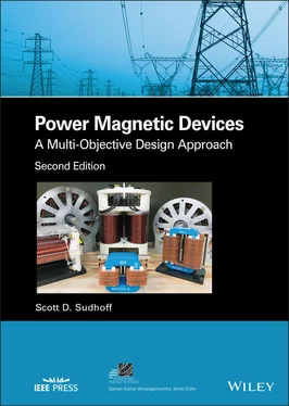
Scott D. Sudhoff - Power Magnetic Devices
Здесь есть возможность читать онлайн «Scott D. Sudhoff - Power Magnetic Devices» — ознакомительный отрывок электронной книги совершенно бесплатно, а после прочтения отрывка купить полную версию. В некоторых случаях можно слушать аудио, скачать через торрент в формате fb2 и присутствует краткое содержание. Жанр: unrecognised, на английском языке. Описание произведения, (предисловие) а так же отзывы посетителей доступны на портале библиотеки ЛибКат.
- Название:Power Magnetic Devices
- Автор:
- Жанр:
- Год:неизвестен
- ISBN:нет данных
- Рейтинг книги:4 / 5. Голосов: 1
-
Избранное:Добавить в избранное
- Отзывы:
-
Ваша оценка:
- 80
- 1
- 2
- 3
- 4
- 5
Power Magnetic Devices: краткое содержание, описание и аннотация
Предлагаем к чтению аннотацию, описание, краткое содержание или предисловие (зависит от того, что написал сам автор книги «Power Magnetic Devices»). Если вы не нашли необходимую информацию о книге — напишите в комментариях, мы постараемся отыскать её.
Discover a cutting-edge discussion of the design process for power magnetic devices Power Magnetic Devices: A Multi-Objective Design Approach
Power Magnetic Devices
Power Magnetic Devices — читать онлайн ознакомительный отрывок
Ниже представлен текст книги, разбитый по страницам. Система сохранения места последней прочитанной страницы, позволяет с удобством читать онлайн бесплатно книгу «Power Magnetic Devices», без необходимости каждый раз заново искать на чём Вы остановились. Поставьте закладку, и сможете в любой момент перейти на страницу, на которой закончили чтение.
Интервал:
Закладка:
7 Chapter 9Table 9.1 Pseudo‐Code for Calculation of the Fitness FunctionTable 9.2 Pseudo‐Code for Check of Constraints Satisfied Against ImposedTable 9.3 Design SpecificationsTable 9.4 Parameter RangesTable 9.5 Machine Design 38 from Pareto‐Optimal Front
8 Chapter 10Table 10.1 Thermal Nodal Analysis Formulation AlgorithmTable 10.2 Thermal Resistances to AmbientTable 10.3 Electrothermal Analysis AlgorithmTable 10.4 Electromagnet Thermal ParametersTable 10.5 Calculation of Fitness FunctionTable 10.6 Thermal ConductivitiesTable 10.7 Design 65 Data
9 Chapter 12Table 12.1 Parameter Domain
10 Chapter 13Table 13.1 Sample Semiconductor ParametersTable 13.2 Inductor Metamodel Parameters (UI‐Core, P‐Ferrite)Table 13.3 Buck Converter Specifications and A Priori Design ChoicesTable 13.4 Buck Converter Design SpaceTable 13.5 Design 100
11 Chapter 14Table 14.1 Case Study Operating Point DataTable 14.2 Three‐Phase I‐Core Inductor SpecificationsTable 14.3 Three‐Phase I‐Core Inductor Design SpaceTable 14.4 Design 100
12 Chapter 15Table 15.1 UR‐Core Common‐Mode Inductor SpecificationsTable 15.2 UR‐Core Three‐Phase Inductor Design SpaceTable 15.3 Design 75
13 Chapter 16Table 16.1 Domain list for Figure 16.4Table 16.2 Node list for Figure 16.4Table 16.3 Basis function coefficients
14 Appendix ATable A.1 Conductor DataTable A.2 American Wire Gauge Wire Diameters
15 Appendix BTable B.1 Ferrite Mass Density DataTable B.2 Ferrite μ >B() DataTable B.3 Ferrite MSE Parameters ( B b= 1T, f b= 1 Hz)
16 Appendix CTable C.1 Silicon Steel DataTable C.2 Silicon Steel μ B() DataTable C.3 Silicon Steel MSE Parameters ( B b= 1T, f b= 1 Hz)
17 Appendix DTable D.1 Selected Magnet Data
List of Illustrations
1 Chapter 1 Figure 1.1 A manual design process. Figure 1.2 Optimization‐based design process. Figure 1.3 Function properties. Figure 1.4 Definition of a convex set. Figure 1.5 Definition of a convex function. Figure 1.6 Deoxyribonucleic acid (DNA). Figure 1.7 Meiosis. Figure 1.8 Canonical genetic algorithm. Figure 1.9 Chromosome crossover, segregation, and mutation in Example 1.5B.... Figure 1.10 Single‐point crossover. Figure 1.11 Single‐point simple‐blend crossover. Figure 1.12 Total mutation. Figure 1.13 Fitness and gene values for Example 1.6A. Figure 1.14 Enhanced real‐coded genetic algorithm. Figure 1.15 Motor performance objective space. Figure 1.16 Pareto‐optimal set and front. Figure 1.17 Calculation of Pareto‐optimal front with ε‐constraint method. Figure 1.18 Application of Kung’s method. Figure 1.19 Crowding distance. Figure 1.20 Elitist nondominated sorting genetic algorithm (NSGA‐II). Figure 1.21 Constraint functions. Figure 1.22 UI‐core inductor. Figure 1.23 Single‐objective optimization study. Figure 1.24 UI‐core design. Figure 1.25 Multi‐objective optimization results. Figure 1.26 Sample design from Pareto‐optimal front. Figure 1.27 Sample design from Pareto‐optimal front.
2 Chapter 2 Figure 2.1 Ampere’s law. Figure 2.2 Calculation of flux. Figure 2.3 Atomic magnetic moment arrangements. Figure 2.4 B–H characteristic of ferromagnetic and ferrimagnetic mater... Figure 2.5 B − H Characteristic of a M47 silicon steel. Figure 2.6 Permeability functions for a M47 silicon steel. Figure 2.7 r( B ) for a M47 silicon steel sample. Figure 2.8 Fields in a material sample “a.” Figure 2.9 UI‐core inductor. Figure 2.10 Construction of the MEC. Figure 2.11 Simplified magnetic equivalent circuit for a UI‐core inductor. Figure 2.12 Flux linkage versus current. Figure 2.13 Measured and predicted λ − i characteristics. Figure 2.14 Measurement of λ − i characteristics. Figure 2.15 Fringing Flux. Figure 2.16 Field components at air‐core interface. Figure 2.17 Calculation of fringing flux. Figure 2.18 Measured and predicted λ − i characteristics including frin... Figure 2.19 Leakage flux. Figure 2.20 Toroidal geometry. Figure 2.21 Horizontal and vertical slot leakage flux. Figure 2.22 Exterior adjacent leakage flux (approach 1). Figure 2.23 Exterior adjacent leakage flux (approach 2). Figure 2.24 Exterior isolated leakage flux. Figure 2.25 Magnetic equivalent circuit with leakage flux permeances. Figure 2.26 A standard branch. Figure 2.27 Sample MEC. Figure 2.28 Sample MEC Figure 2.29 Simple nonlinear MEC. Figure 2.30 Residual for nodal analysis. Figure 2.31 Residual using mesh analysis. Figure 2.32 Measured and predicted λ − i characteristics including frin...Figure 2.33 B‐H and M‐H Characteristics of PM Material.Figure 2.34 Permanent magnet MEC element.Figure 2.35 Permanent magnet configuration.
3 Chapter 3Figure 3.1 Common inductor architectures.Figure 3.2 Example of a coil.Figure 3.3 Cross‐section of coil.Figure 3.4 Bobbin wound coil.Figure 3.5 UI‐Core inductor.Figure 3.6 UI‐Core inductor Pareto‐optimal front.Figure 3.7 Final population gene distribution.Figure 3.8 Current density versus mass.Figure 3.9 Conductor count versus mass.Figure 3.10 Dimensions versus mass.Figure 3.11 Design 50.
4 Chapter 4Figure 4.1 Field energy and co‐energy.Figure 4.2 Excitation of a single branch.
5 Chapter 5Figure 5.1 Possible electromagnet arrangements.Figure 5.2 EI‐core electromagnet.Figure 5.3 EI‐core magnetic equivalent circuit.Figure 5.4 Slot leakage path.Figure 5.5 Reduced magnetic equivalent circuit.Figure 5.6 Flux linkage versus current.Figure 5.7 Force versus current.Figure 5.8 Force over power loss versus current.Figure 5.9 Electromagnetic door latch.Figure 5.10 Pareto‐optimal front between volume and loss.Figure 5.11 Gene distribution plot for the electromagnet.Figure 5.12 Current density versus volume for electromagnet.Figure 5.13 Conductor count versus volume for electromagnet.Figure 5.14 Core widths versus volume for electromagnet.Figure 5.15 Geometrical parameters versus volume for electromagnet.Figure 5.16 Geometrical parameters versus volume for electromagnet.Figure 5.17 Effects of wire size descritization on Pareto‐optimal front.Figure 5.18 Effects of wire size discretization on current density.
6 Chapter 6Figure 6.1 Calculation of eddy current losses.Figure 6.2 Top view of test configuration.Figure 6.3 Excitation‐normalized power loss versus frequency.Figure 6.4 Magnetic domains.Figure 6.5 B–H characteristics of a ferrite material MN80C.Figure 6.6 Large uniformly wound toroid.Figure 6.7 Hysteresis characteristic.Figure 6.8 Minor loop behavior.Figure 6.9 Flux density waveforms.Figure 6.10 Loss components versus frequency.Figure 6.11 Epstein frame.Figure 6.12 Single‐ and double‐sheet testers.Figure 6.13 Toroidal tester.Figure 6.14 Impact of laser cutting.Figure 6.15 Determining the anhysteretic characteristic.Figure 6.16 Characterization waveforms in example 6.5A.Figure 6.17 Sense winding flux linkage versus magnetizing current in example...Figure 6.18 B – H characteristic in example 6.5A.Figure 6.19 Example 6.5B characterization of μ B( B ).Figure 6.20 Example 6.8A measured and fitted losses.Figure 6.21 Hysteron behavior.Figure 6.22 Example magnetization states.Figure 6.23 Incremental magnetization.Figure 6.24 Trajectories predicted by the extended Jiles–Atherton model.Figure 6.25 Alternate path for eddy current derivation.
7 Chapter 7Figure 7.1 Transformer types.Figure 7.2 Cross section of one leg of core type transformer.Figure 7.3 Elementary transformer.Figure 7.4 Transformer magnetic equivalent circuit.Figure 7.5 T‐equivalent circuit.Figure 7.6 Circuit for Example 7.3A.Figure 7.7 Modified T‐equivalent circuit.Figure 7.8 Core‐type transformer cross section.Figure 7.9 End leg cross section with coils.Figure 7.10 Coil construction.Figure 7.11 Core type transformer magnetic equivalent circuit.Figure 7.12 Reduced magnetic equivalent circuit.Figure 7.13 Core type transformer leakage paths.Figure 7.14 Division of winding into interior and exterior portions.Figure 7.15 Consideration of a vertical leakage path.Figure 7.16 Leakage flux paths.Figure 7.17 Exterior secondary leakage flux paths.Figure 7.18 Transformer design Pareto‐optimal front.Figure 7.19 Parameter distribution .Figure 7.20 Design 100 cross sections.Figure 7.21 Primary flux linkage versus current.Figure 7.22 No‐load flux density waveforms.
Читать дальшеИнтервал:
Закладка:
Похожие книги на «Power Magnetic Devices»
Представляем Вашему вниманию похожие книги на «Power Magnetic Devices» списком для выбора. Мы отобрали схожую по названию и смыслу литературу в надежде предоставить читателям больше вариантов отыскать новые, интересные, ещё непрочитанные произведения.
Обсуждение, отзывы о книге «Power Magnetic Devices» и просто собственные мнения читателей. Оставьте ваши комментарии, напишите, что Вы думаете о произведении, его смысле или главных героях. Укажите что конкретно понравилось, а что нет, и почему Вы так считаете.


