Mohammad H. Sadraey - Introduction to UAV Systems
Здесь есть возможность читать онлайн «Mohammad H. Sadraey - Introduction to UAV Systems» — ознакомительный отрывок электронной книги совершенно бесплатно, а после прочтения отрывка купить полную версию. В некоторых случаях можно слушать аудио, скачать через торрент в формате fb2 и присутствует краткое содержание. Жанр: unrecognised, на английском языке. Описание произведения, (предисловие) а так же отзывы посетителей доступны на портале библиотеки ЛибКат.
- Название:Introduction to UAV Systems
- Автор:
- Жанр:
- Год:неизвестен
- ISBN:нет данных
- Рейтинг книги:5 / 5. Голосов: 1
-
Избранное:Добавить в избранное
- Отзывы:
-
Ваша оценка:
Introduction to UAV Systems: краткое содержание, описание и аннотация
Предлагаем к чтению аннотацию, описание, краткое содержание или предисловие (зависит от того, что написал сам автор книги «Introduction to UAV Systems»). Если вы не нашли необходимую информацию о книге — напишите в комментариях, мы постараемся отыскать её.
The latest edition of the leading resource on unmanned aerial vehicle systems
A thorough introduction to the history of unmanned aerial vehicles, including their use in various conflicts, an overview of critical UAV systems, and the Predator/Reaper A comprehensive exploration of the classes and missions of UAVs, including several examples of UAV systems, like Mini UAVs, UCAVs, and quadcopters Practical discussions of air vehicles, including coverage of topics like aerodynamics, flight performance, stability, and control In-depth examinations of propulsion, loads, structures, mission planning, control systems, and autonomy Introduction to UAV Systems
Design of Unmanned Aerial Systems
Introduction to UAV Systems
Introduction to UAV Systems — читать онлайн ознакомительный отрывок
Ниже представлен текст книги, разбитый по страницам. Система сохранения места последней прочитанной страницы, позволяет с удобством читать онлайн бесплатно книгу «Introduction to UAV Systems», без необходимости каждый раз заново искать на чём Вы остановились. Поставьте закладку, и сможете в любой момент перейти на страницу, на которой закончили чтение.
Интервал:
Закладка:
The bird can make the negative thrust during the up stroke even smaller by bending its wings during the up stroke, as shown in Figure 3.22. This largely eliminates the forces induced by the outer portions of the wings, which are the most important contributors to thrust, while preserving much of the lift produced near the wing roots.
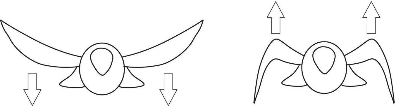
Figure 3.22 Wing articulation
This simplified description of how flapping wings can allow a bird to fly is as far as we are going to go in this introductory text. There are some significant differences between how birds fly and how insects fly, and not all birds fly in exactly the same way. In the early days of heavier‐than‐air flight, there were many attempts to use flapping wings to lift a human passenger. All were unsuccessful. As interest has increased in recent years in small, even tiny, UAVs, the biomechanics of bird and insect flight are being closely re‐examined and recently have been successfully emulated by machines.
3.13 Aerodynamic Efficiency
One of the important parameters in a cruising flight is the aerodynamic efficiency. This parameter is directly a function of the aircraft lift‐to‐drag ratio. One of the objectives in aerodynamic design of an air vehicle is to produce the maximum lift with a minimum drag. The aerodynamic efficiency of an air vehicle relies heavily on the section of its wing/tail; that is “ airfoil .”
Using the equations for lift and drag, one can readily prove the following relation for the maximum lift‐to‐drag ratio:
(3.15) 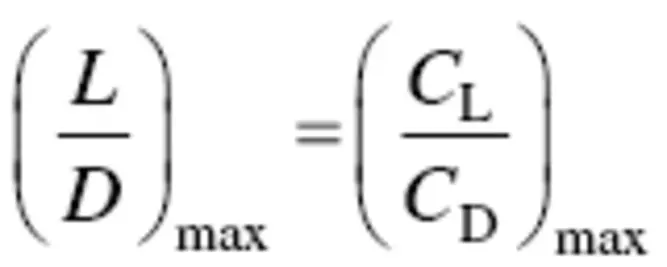
The lift versus drag curve is further discussed in Section 3.5. Reference [12] has derived the following expression for the maximum lift‐to‐drag coefficients ratio:
(3.16) 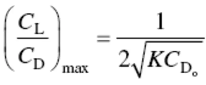
With this relationship, one is able to evaluate the maximum lift‐to‐drag ratio of any aircraft. The only necessary information is the aircraft zero lift drag coefficient ( C Do) and the induced drag correction factor ( K ). Graphically, the maximum L / D corresponds to the slope of the tangent to the C D‐ C Lfigure (drag polar), which is shown in Figures 3.7and 3.13. Figure 3.7shows the two‐dimensional drag coefficient ( C d) and the moment coefficient as a function of the lift coefficient ( C l) for the NACA 23021 airfoil.
Aerodynamic efficiency ( η E) is defined as the ratio of the difference between lift and drag over the lift:
(3.17) 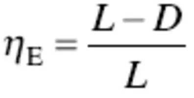
In a cruising flight, lift is equal to the aircraft weight ( L = W ). Thus,
(3.18) 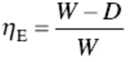
The maximum aerodynamic efficiency is
(3.19) 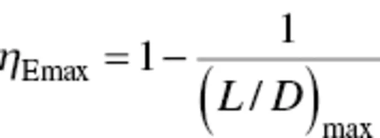
Equations (3.19)and (3.16)reveal that the following factors play an important role in air vehicle aerodynamic efficiency: (1) aircraft zero lift drag coefficient ( C Do) and (2) induced drag correction factor ( K ). Furthermore, due to Equation (3.6), the Oswald span efficiency factor ( e ) and the wing aspect ratio ( AR ) are also impacting the aerodynamic efficiency.
As a conclusion, in order to increase the air vehicle maximum aerodynamic efficiency, one must: (1) decrease the aircraft zero lift drag coefficient and (2) increase the wing aspect ratio. High aspect ratio wings (long and slender) are conducive to good range and endurance. Short stubby (low AR ) wings generate low aerodynamic efficiency (i.e., penalize the length of time‐on‐target during reconnaissance missions), but are good for highly maneuverable fighters.
The wing aspect ratio for the MALE UAV General Atomics MQ‐1 Predator (see Figure 11.1) wing is about 22.5, while for the HALE UAV Northrop Grumman RQ‐4 Global Hawk (see Figure 1.4) wing is about 25. The wing aspect ratio for the small UAV AeroVironment RQ‐11 Raven (see Figure 18.11) is 3.7.
Example 3.1
A MALE UAV with a turbofan engine has a zero‐lift drag coefficient of 0.021 and an induced drag factor of 0.04. Determine the maximum aerodynamic efficiency of the air vehicle.
Solution:
from (3.16) 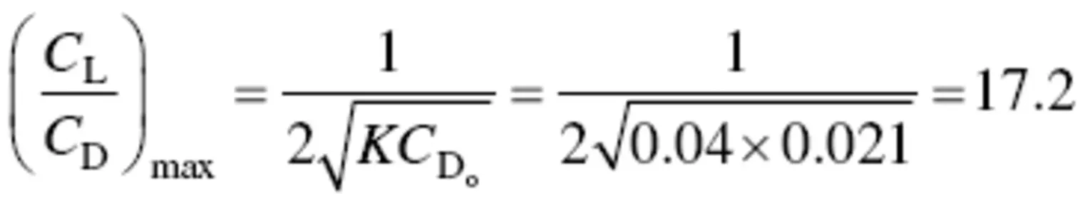
from (3.19) 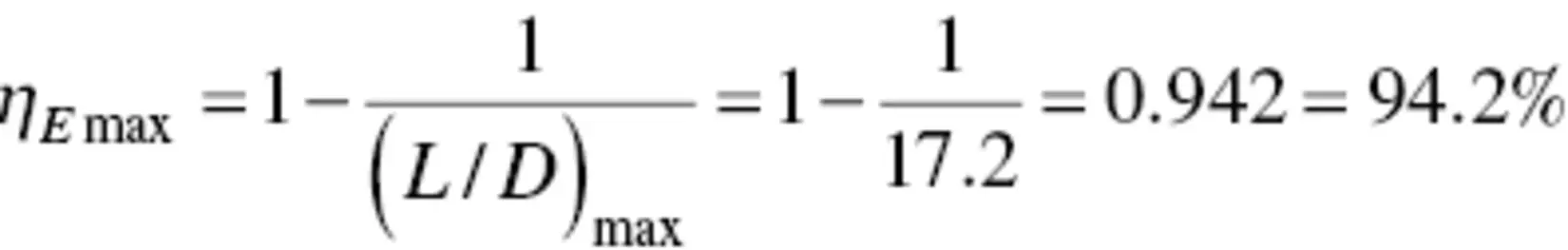
Questions
1 Define aerodynamics.
2 Name primary forces that act on an air vehicle.
3 Name elements that make considerable contributions on air vehicle’s aerodynamic features.
4 What is the primary aerodynamic function of a wing?
5 Name two aerodynamic forces.
6 The aerodynamic forces of lift and drag are functions of a number of factors. What are they?
7 Define lift.
8 Draw the side‐view of a wing at an angle of attack. In the figure, illustrate: (1) total aerodynamic force, (2) lift, (3) drag, and (4) name and the location of the forces.
9 Define Mach number.
10 List the flight regimes, when the airspeed is compared with the speed of sound. Briefly define each one.
11 What are the two most important parameters of an airfoil?
12 Provide at least five geometric parameters of an airfoil.
13 Briefly compare the patterns of air pressure over a two‐dimensional airfoil and a three‐dimensional wing.
14 What do NACA and NASA stand for?
15 Define streamline.
16 What is the thickness‐to‐chord ratio of the NACA airfoil 23021?
17 What is the lift coefficient of the NACA 23021 airfoil at an angle of attack of 10 degrees when R = 3 × 10⁶?
18 What is the maximum lift coefficient of the NACA 23021 airfoil when R = 3×10⁶?
19 What is the minimum drag coefficient of the NACA 23021 airfoil when R = 8.9 × 10⁶?
20 What is the drag coefficient of the NACA 23021 airfoil when the lift coefficient is 0.2 at R = 8.9 × 10⁶?
21 What airfoil is used on the wing of the Northrop Grumman RQ‐4 Global Hawk?
22 What airfoil is used on the wing of the General Atomics MQ‐1 Predator?
23 Compare the static pressure of the top and bottom surfaces for a positive cambered airfoil at a positive angle of attack. Draw a figure.
24 Why is a vortex generated at each wing tip?
25 Briefly describe how the lift is generated on a wing.
26 Draw a typical drag polar and discuss its characteristics.
27 The drag coefficient is the sum of two terms. What are they?
Читать дальшеИнтервал:
Закладка:
Похожие книги на «Introduction to UAV Systems»
Представляем Вашему вниманию похожие книги на «Introduction to UAV Systems» списком для выбора. Мы отобрали схожую по названию и смыслу литературу в надежде предоставить читателям больше вариантов отыскать новые, интересные, ещё непрочитанные произведения.


Обсуждение, отзывы о книге «Introduction to UAV Systems» и просто собственные мнения читателей. Оставьте ваши комментарии, напишите, что Вы думаете о произведении, его смысле или главных героях. Укажите что конкретно понравилось, а что нет, и почему Вы так считаете.