Mohammad H. Sadraey - Introduction to UAV Systems
Здесь есть возможность читать онлайн «Mohammad H. Sadraey - Introduction to UAV Systems» — ознакомительный отрывок электронной книги совершенно бесплатно, а после прочтения отрывка купить полную версию. В некоторых случаях можно слушать аудио, скачать через торрент в формате fb2 и присутствует краткое содержание. Жанр: unrecognised, на английском языке. Описание произведения, (предисловие) а так же отзывы посетителей доступны на портале библиотеки ЛибКат.
- Название:Introduction to UAV Systems
- Автор:
- Жанр:
- Год:неизвестен
- ISBN:нет данных
- Рейтинг книги:5 / 5. Голосов: 1
-
Избранное:Добавить в избранное
- Отзывы:
-
Ваша оценка:
Introduction to UAV Systems: краткое содержание, описание и аннотация
Предлагаем к чтению аннотацию, описание, краткое содержание или предисловие (зависит от того, что написал сам автор книги «Introduction to UAV Systems»). Если вы не нашли необходимую информацию о книге — напишите в комментариях, мы постараемся отыскать её.
The latest edition of the leading resource on unmanned aerial vehicle systems
A thorough introduction to the history of unmanned aerial vehicles, including their use in various conflicts, an overview of critical UAV systems, and the Predator/Reaper A comprehensive exploration of the classes and missions of UAVs, including several examples of UAV systems, like Mini UAVs, UCAVs, and quadcopters Practical discussions of air vehicles, including coverage of topics like aerodynamics, flight performance, stability, and control In-depth examinations of propulsion, loads, structures, mission planning, control systems, and autonomy Introduction to UAV Systems
Design of Unmanned Aerial Systems
Introduction to UAV Systems
Introduction to UAV Systems — читать онлайн ознакомительный отрывок
Ниже представлен текст книги, разбитый по страницам. Система сохранения места последней прочитанной страницы, позволяет с удобством читать онлайн бесплатно книгу «Introduction to UAV Systems», без необходимости каждый раз заново искать на чём Вы остановились. Поставьте закладку, и сможете в любой момент перейти на страницу, на которой закончили чтение.
Интервал:
Закладка:
The boundary layer – at subsonic speeds – is often composed of three regions beginning at the leading edge of a surface: (1) the laminar region where each layer or lamina slips over the adjacent layer in an orderly manner, creating a well‐defined shear force in the fluid, (2) a transition region, and (3) a turbulent region, where the particles of fluid mix with each other in a random way, creating turbulence and eddies. The transition region is where the laminar region begins to become turbulent. The shear force in the laminar region and the swirls and eddies in the turbulent region both create drag, but with different physical processes. The cross‐section of a typical boundary layer might look like Figure 3.16.
Figure 3.17illustrates a typical boundary layer (BL) over a wing/tail airfoil, where two laminar and turbulent portions are distinguished. As we move along the flow, the thickness of the BL is increased, and the flow becomes more and more turbulent.
The shearing stress that the fluid exerts on the surface is called skin friction and is an important component of the overall drag. The two distinct regions in the boundary layer (laminar and turbulent) depend on the velocity of the fluid, the surface roughness, the fluid density, and the fluid viscosity. These factors, with the exception of the surface roughness, were combined by Osborne Reynolds in 1883 into a formula that has become known as the Reynolds number, which mathematically is expressed as
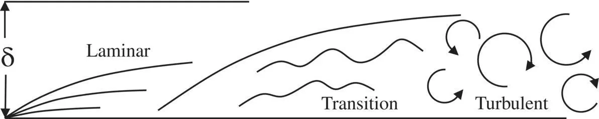
Figure 3.16 Typical boundary layer over a flat surface
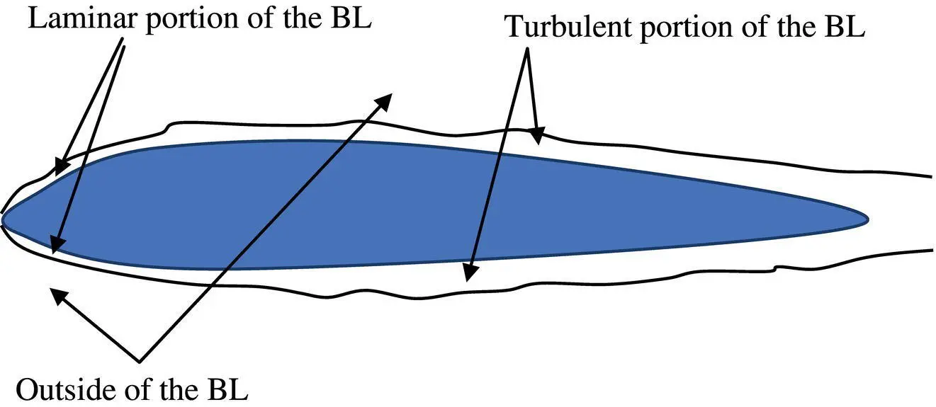
Figure 3.17 Typical boundary layer over a wing/tail airfoil
(3.10) 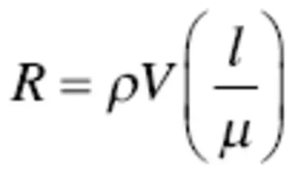
where ρ is fluid (here, air) density, V is air velocity, μ is air viscosity, and l is a characteristic length.
In aeronautical work, the characteristic length is usually taken as the chord of a wing surface. The Reynolds number is an important indicator of whether the boundary layer is in a laminar or turbulent condition. Laminar flow creates considerably less drag than turbulent, but nevertheless causes difficulties with small surfaces, as we shall learn later. Typical Reynolds numbers for various air vehicles – including a bird and an insect – are shown in Table 3.1.
Laminar flow causes drag by virtue of the friction between layers and is particularly sensitive to the surface condition. Normally, laminar flow results in less drag and is desirable. The drag of the turbulent boundary layer is caused by a completely different mechanism (e.g., vortex) that depends on knowledge of viscous flow.
In any flow, two fundamental laws are always applicable: (1) energy conservation law and (2) mass conservation law. For an incompressible flow ( M < 0.3), the energy conservation law indicates that for an ideal fluid (no friction), the sum of the static pressure ( P ) and the dynamic pressure ( q ), where 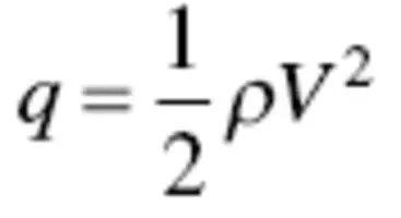 , is constant:
(3.11) 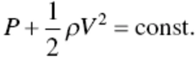
Applying this principle to flow in a duct (e.g., convergent–divergent duct), with the first half representing the first part of an airplane wing, the distribution of pressure and velocity in a boundary layer can be analyzed. The flow inside a duct is very similar to a flow over and under a wing.
In an incompressible flow where the air density remains constant along the flow, this equation – for two arbitrary points (1 and 2) – is expanded as
(3.12) 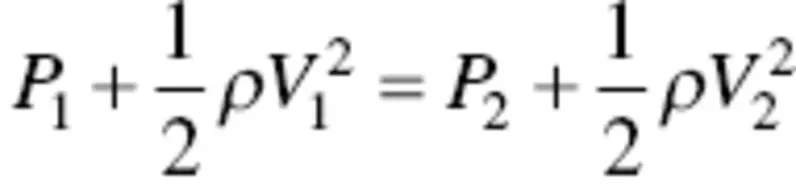
This equation is referred to as Bernoulli’s equation. As the fluid (assumed to be incompressible) moves through the duct or over a wing, its velocity increases (because of the law of conservation of mass) and, as a consequence of Bernoulli’s equation, its pressure decreases, causing what is known as a favorable pressure gradient. The pressure gradient is favorable because it helps push the fluid in the boundary layer on its way.
Table 3.1 Typical Reynolds numbers
| No. | Air Vehicle Type | Reynolds Number |
|---|---|---|
| 1 | Large subsonic UAVs | 5,000,000 |
| 2 | Small UAVs | 400,000 |
| 3 | Mini‐UAVs – Quadcopters | 50,000 |
| 4 | A Seagull | 100,000 |
| 5 | A Gliding Butterfly | 7,000 |
After reaching a maximum velocity (usually at the maximum thickness point of an airfoil or the minimum diameter of a duct), the fluid begins to slow. If the slope of the divergent section is high, the flow consequently forms an unfavorable pressure gradient (i.e., hinders the boundary layer flow) as seen by the velocity profiles in Figure 3.18.
Small characteristic lengths and low speeds result in low Reynolds numbers and consequently laminar flow, which is normally a favorable condition. A point is reached in this situation where the unfavorable pressure gradient actually stops the flow within the boundary layer and eventually reverses it. The flow stoppage and reversal results in the formation of turbulence, vortices, and in general a random mixing of the fluid particles.
At this point, the boundary layer detaches or separates from the surface and creates a turbulent wake. This phenomenon is called separation, and the drag associated with it is called vortex drag. Whether the boundary layer is turbulent or laminar depends on the Reynolds number, as does the friction coefficient, as shown in Figure 3.19.
It would seem that laminar flow is always desired (for less pressure drag), and usually it is, but it can become a problem when dealing with very small UAVs that fly at low speeds. The favorable and unfavorable pressure gradients previously described also exist at very low speeds, making it possible for the laminar boundary layer to separate and reattach itself. This keeps the surface essentially in the laminar flow region, but creates a bubble of fluid within the boundary layer. This is called laminar separation and is a characteristic of the wings of very small, low‐speed airplanes (e.g., small model airplanes and very small UAVs).
The bubble can move about on the surface of the wing, depending on the angle of attack, speed, and surface roughness. It can grow in size and then can burst in an unexpected manner. The movement and bursting of the bubble disrupts the pressure distribution on the surface of the wing and can cause serious and sometimes uncontrollable air‐vehicle motion. This has not been a problem with larger, higher speed airplanes because most of the wings of these airplanes are in turbulent flow boundary layers due to the high Reynolds number at which they operate.
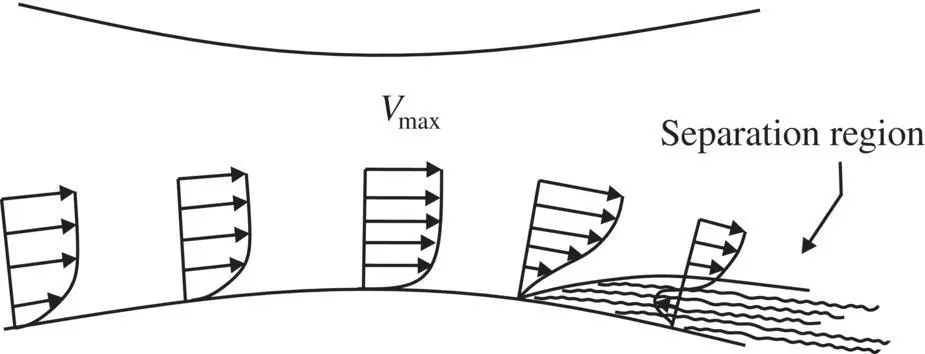
Figure 3.18 Boundary layer velocity profile inside a convergent–divergent duct
Читать дальшеИнтервал:
Закладка:
Похожие книги на «Introduction to UAV Systems»
Представляем Вашему вниманию похожие книги на «Introduction to UAV Systems» списком для выбора. Мы отобрали схожую по названию и смыслу литературу в надежде предоставить читателям больше вариантов отыскать новые, интересные, ещё непрочитанные произведения.


Обсуждение, отзывы о книге «Introduction to UAV Systems» и просто собственные мнения читателей. Оставьте ваши комментарии, напишите, что Вы думаете о произведении, его смысле или главных героях. Укажите что конкретно понравилось, а что нет, и почему Вы так считаете.