Mohammad H. Sadraey - Introduction to UAV Systems
Здесь есть возможность читать онлайн «Mohammad H. Sadraey - Introduction to UAV Systems» — ознакомительный отрывок электронной книги совершенно бесплатно, а после прочтения отрывка купить полную версию. В некоторых случаях можно слушать аудио, скачать через торрент в формате fb2 и присутствует краткое содержание. Жанр: unrecognised, на английском языке. Описание произведения, (предисловие) а так же отзывы посетителей доступны на портале библиотеки ЛибКат.
- Название:Introduction to UAV Systems
- Автор:
- Жанр:
- Год:неизвестен
- ISBN:нет данных
- Рейтинг книги:5 / 5. Голосов: 1
-
Избранное:Добавить в избранное
- Отзывы:
-
Ваша оценка:
Introduction to UAV Systems: краткое содержание, описание и аннотация
Предлагаем к чтению аннотацию, описание, краткое содержание или предисловие (зависит от того, что написал сам автор книги «Introduction to UAV Systems»). Если вы не нашли необходимую информацию о книге — напишите в комментариях, мы постараемся отыскать её.
The latest edition of the leading resource on unmanned aerial vehicle systems
A thorough introduction to the history of unmanned aerial vehicles, including their use in various conflicts, an overview of critical UAV systems, and the Predator/Reaper A comprehensive exploration of the classes and missions of UAVs, including several examples of UAV systems, like Mini UAVs, UCAVs, and quadcopters Practical discussions of air vehicles, including coverage of topics like aerodynamics, flight performance, stability, and control In-depth examinations of propulsion, loads, structures, mission planning, control systems, and autonomy Introduction to UAV Systems
Design of Unmanned Aerial Systems
Introduction to UAV Systems
Introduction to UAV Systems — читать онлайн ознакомительный отрывок
Ниже представлен текст книги, разбитый по страницам. Система сохранения места последней прочитанной страницы, позволяет с удобством читать онлайн бесплатно книгу «Introduction to UAV Systems», без необходимости каждый раз заново искать на чём Вы остановились. Поставьте закладку, и сможете в любой момент перейти на страницу, на которой закончили чтение.
Интервал:
Закладка:
(3.1) 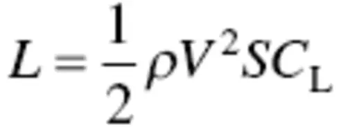
(3.2) 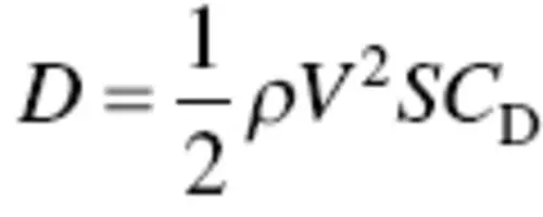
where ρ is air density, V is velocity, S is the wing planform area, and C Land C Dare the lift and drag coefficients respectively. The calculations of lift and drag coefficients will be presented in the coming sections.
The lift force or simply lift is always defined as the component of the aerodynamic force perpendicular to the relative wind. The drag is always defined as the component of the aerodynamic force parallel to the relative wind ( V ∞). In other words, lift is always perpendicular and drag is always parallel to the relative wind. Figure 3.2shows an airfoil section and the directions of lift and drag.
In reality, the aerodynamic force is located at the center of pressure (cp), which is moving with the variations of angle of attack ( α ). However, the aerodynamic center (ac) which is frequently selected to be the center of lift, is located nearly at the quarter chord (i.e., 1/4 of C ). The pitching moment is the bi‐product of moving the location of aerodynamic force from cp to ac. The moment can be taken with respect to any point, but traditionally is taken about a point 25% rearward of the wing leading edge, known as the quarter chord. The aerodynamic center has a desired property – the variation of moment coefficient with respect to the angle of attack is zero (i.e., moment coefficient remains constant).
3.3 Mach Number
It is customary to compare the speed of an air vehicle ( V ) with the speed of sound ( a ). The Mach number is defined as the ratio of airspeed over the speed of sound:
(3.3) 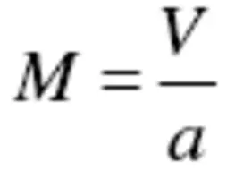
The speed of sound at the sea level standard condition is 340 m/s. M is used to define four different flight regimes for airspeed: (1) subsonic, (2) transonic, (3) supersonic, and (4) hypersonic.
When the flight speed is less than the speed of sound – where M < 1 – it is defined as subsonic speed. When 0.8 ≤ M ≤ 1.2, the flight regime is loosely defined as transonic. If the flight speed is less than the speed of sound, but M is sufficiently near 1, the airflow expansion over the top surfaces of the wing/tail/fuselage may result in locally supersonic regions. A flowfield where M > 1 everywhere is defined as supersonic. At supersonic speeds, a shock wave (e.g., normal, oblique, and bow) is created by nature to adjust the flow properties (e.g., air pressure and temperature).
The flow regime for M > 5 is given a special label, hypersonic flow. For values of M > 5, the shock wave is very close to the surface, and the flowfield between the shock and the body (the shock layer) becomes very hot indeed, hot enough to dissociate or even ionize the gas. The aerodynamic characteristics of an air vehicle is strongly a function of Mach number, some of which will be discussed in this chapter.
3.4 Airfoil
The most important element of a lifting surface (e.g., wing/tail) for aerodynamic purposes is its cross‐section or airfoil. Any section of the wing cut by a plane parallel to the aircraft xz plane is called an airfoil. It usually looks like a positive cambered section where the thicker part is in front of the airfoil. A typical airfoil section is shown in Figure 3.3, where several geometric parameters are illustrated. The leading edge is often curved (for a subsonic air vehicle) and the trailing ledge is sharp.
If the mean camber line is a straight line, the airfoil is referred to as symmetric airfoil; otherwise it is called a cambered airfoil. The camber of airfoil is usually positive.
Two of the most important parameters of an airfoil are camber and the thickness‐to‐chord ratio. The wing/tail is a three‐dimensional component, while the airfoil is a two‐dimensional (2d) section. Because of the airfoil section, two other outputs of the airfoil, and consequently the wing/tail, are drag and pitching moment.

Figure 3.3 Airfoil geometric parameters

Figure 3.4 Infinite span wing
Any particular airfoil cross‐sectional shape has a characteristic set of curves for the coefficients of lift, drag, and moment that depend on the angle of attack and Reynolds number. These are determined from wind tunnel tests and are designated by lowercase subscripts.
Basic aerodynamic data are usually measured from a wing that extends from wall to wall in the wind tunnel, as shown in Figure 3.4. Extending the wing from wall to wall prevents spanwise airflow and results in a true two‐dimensional pattern of air pressure. This concept is called the infinite‐span wing, because a wing with an infinite span could not have air flowing around its tips, creating spanwise flow and disturbing the two‐dimensional pressure pattern that is a necessary starting point for describing the aerodynamic forces on a wing. A real airplane wing has a finite span, and often tapers and twists. The analysis of aerodynamic forces begins with the two‐dimensional coefficients, which then are adjusted to account for the three‐dimensional nature of the real wing.
Figure 3.4also illustrates a few of the infinite number of streamlines around a wing. A streamline is a curve in the flowfield that is tangent to the local velocity vector at every point along the curve. Upstream of the wing, the flow is uniform with a constant velocity.
In the 1950s, airfoils were classified by the National Advisory Committee for Aeronautics (NACA), the forerunner of the present NASA, and were cataloged using a four/five digits code. The details of NACA airfoils have been presented in a book published by Abbott and Von Donehoff [9]. The NACA airfoils are one of the most common and one of the oldest airfoil families.
Airfoil cross‐sections and their two‐dimensional coefficients were classified in a standard system maintained by the NACA (predecessor of the present National Aeronautics and Space Administration (NASA)) and identified by a NACA numbering system, which is described in most aerodynamic textbooks. Figures 3.5to 3.7show the data contained in the summary charts of the NASA database for NACA airfoil 23021 as an example of the information available on many airfoil designs.
Figure 3.5shows the profile of a cross‐section of this airfoil which has a thickness‐to‐chord ratio of 21%. The x (horizontal) and y (vertical) coordinates of the surface are plotted as x/c and y/c , where c is the chord of the airfoil, its total length from nose to tail.
Two‐dimensional lift and moment coefficients for this airfoil are plotted as a function of angle of attack in Figure 3.6. Two‐dimensional drag and moment coefficients for this airfoil are plotted as a function of the lift coefficient in Figure 3.7. Moments and how they are specified are further discussed in Section 3.5. The moment coefficient in the plot is around an axis located at the quarter‐cord, as mentioned previously.
Читать дальшеИнтервал:
Закладка:
Похожие книги на «Introduction to UAV Systems»
Представляем Вашему вниманию похожие книги на «Introduction to UAV Systems» списком для выбора. Мы отобрали схожую по названию и смыслу литературу в надежде предоставить читателям больше вариантов отыскать новые, интересные, ещё непрочитанные произведения.


Обсуждение, отзывы о книге «Introduction to UAV Systems» и просто собственные мнения читателей. Оставьте ваши комментарии, напишите, что Вы думаете о произведении, его смысле или главных героях. Укажите что конкретно понравилось, а что нет, и почему Вы так считаете.